Install the system board
Follow instructions in this section to install the system board. The procedure must be executed by a trained technician.
About this task
Read Installation Guidelines and Safety inspection checklist to ensure that you work safely.
Touch the static-protective package that contains the drive to any unpainted metal surface on the server; then, remove the drive from the package and place it on a static-protective surface.
Go to Drivers and Software download website for ThinkSystem ST50 V3 to see the latest firmware and driver updates for your server.
Go to Update the firmware for more information on firmware updating tools.
Procedure
- Install the system board.
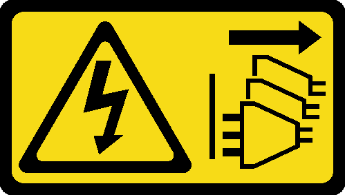
 Tilt the system board, and align the connectors with the corresponding opening on the front of the chassis. Then, gently lower the system board into the chassis, and insert the connectors into the slot on the front of the chassis.
 Slide the system board toward the rear of the chassis until the system board is secured in place.
Figure 1. Installing the system board into the chassis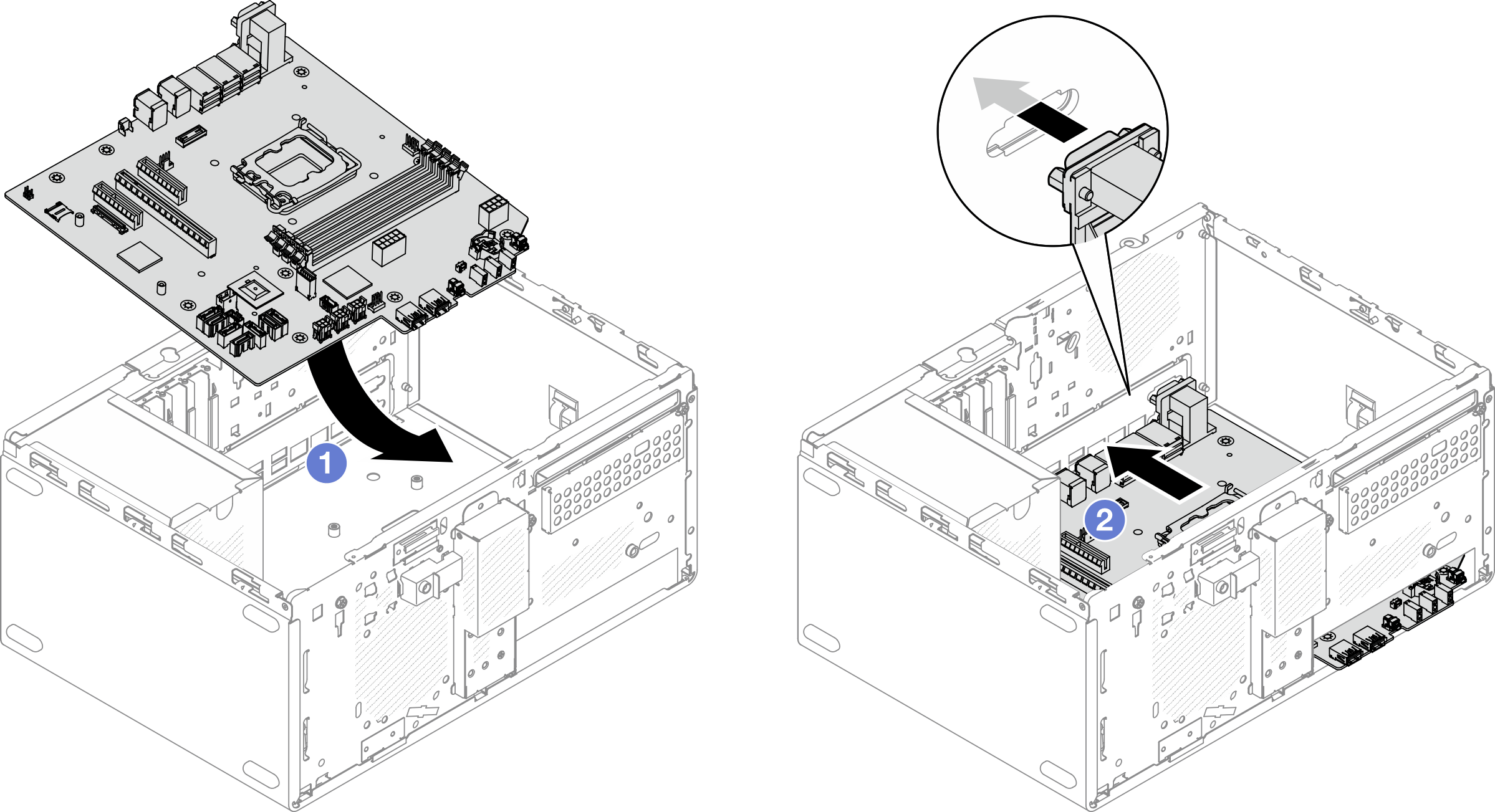
- Secure the system board to the chassis with nine screws in the sequence shown on the illustration below.Figure 2. Installing the system board into the chassis
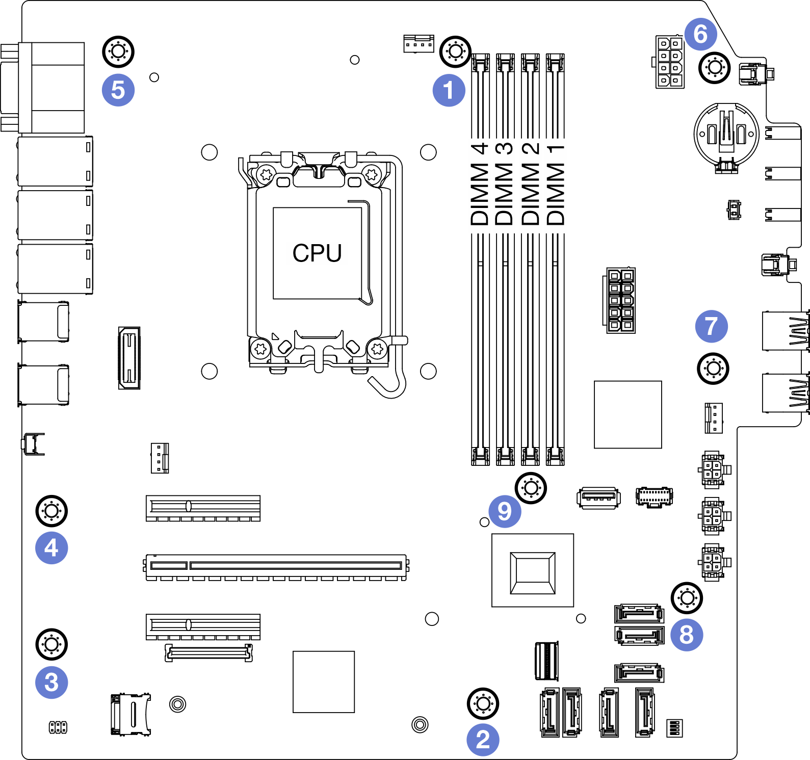
- Install the front I/O bracket.
- There is a small tab on the right side of the front I/O bracket. Place the tab behind the front I/O bracket slot on the chassis.
- Align the guide hole and screw hole on the front I/O bracket with the guide pin and screw slot on the chassis; then, install the front I/O bracket to the chassis.NoteMake sure the small tab on the right side of the front I/O bracket is placed behind the chassis.Figure 3. Installing the front I/O bracket to the chassis
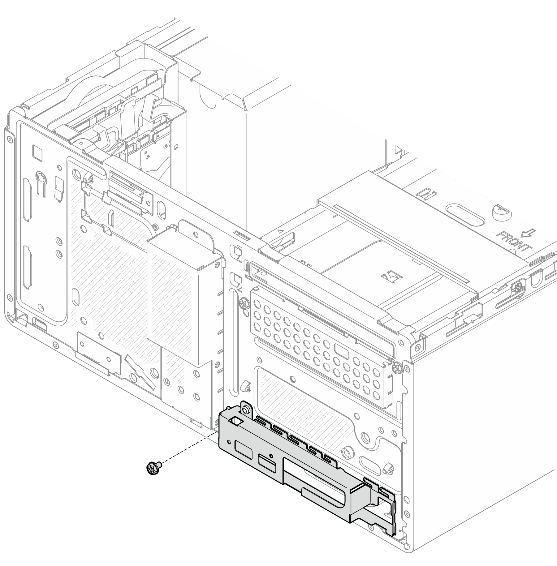
- Fasten the screw to secure the front I/O bracket to the chassis.Figure 4. Securing the front I/O bracket to the chassis
- Reconnect all the required cables to the same connectors on the system board as the defective system board.
Install the firmware and RoT security module. See Install the firmware and RoT security module.
Install the processor. See Install the processor (trained technician only).
Install the memory module. See Install a memory module.
Install the PCIe adapter. See Install a PCIe adapter.
Install the M.2 boot adapter. See Install the M.2 boot adapter.
Install the heat sink and fan module. See Install the heat sink and fan module (trained technician only).
Install the rear system fan. See Install the fan (front and rear).
If applicable, install the drive cage (bay 3). See Install the drive cage (bay 3).
Install the intrusion switch. See Install the intrusion switch.
Install the cage bar. See step 3 in Install the server cover.
If applicable, install the optical drive cage. See Install the optical drive cage.
If applicable, install the optical drive. See Install an optical drive.
Install the front bezel. See Install the front bezel.
Install the server cover. See Install the server cover.
Complete the parts replacement. See Complete the parts replacement.
- Update the vital product data (VPD). See Update the Vital Product Data (VPD). Machine type number and serial number can be found on the ID label. See Identify the server and access the Lenovo XClarity Controller.
- Optionally, enable UEFI Secure Boot. See Enable UEFI Secure Boot.
Demo video