Remove the system board
Follow instructions in this section to remove the system board. The procedure must be executed by a trained technician.
About this task
S002
CAUTION
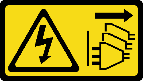
The power-control button on the device and the power switch on the power supply do not turn off the electrical current supplied to the device. The device also might have more than one power cord. To remove all electrical current from the device, ensure that all power cords are disconnected from the power source.
Important
- This task must be operated by trained technicians that are certified by Lenovo Service. Do no attempt to remove or install the part without proper training and qualification.
- When removing the memory modules, label the slot number on each memory module, remove all the memory modules from the system board, and set them aside on a static-protective surface for reinstallation.
- When disconnecting cables, make a list of each cable and record the connectors the cable is connected to, and use the record as a cabling checklist after installing the new system board.
Attention
- Read Installation Guidelines and Safety inspection checklist to ensure that you work safely.
- Power off the server and peripheral devices and disconnect the power cords and all external cables. See Power off the server.
- If the server is in a rack, remove it from the rack. See Remove the server from rack.
- Remove any locking device that secures the server, such as a Kensington lock or a padlock.
- Place the server on its side with the cover up.
Procedure
- Remove the front I/O bracket.
- Remove the screw the secures the front I/O bracket to the chassis.Figure 1. Removing the screw that secures the front I/O bracket to the chassis
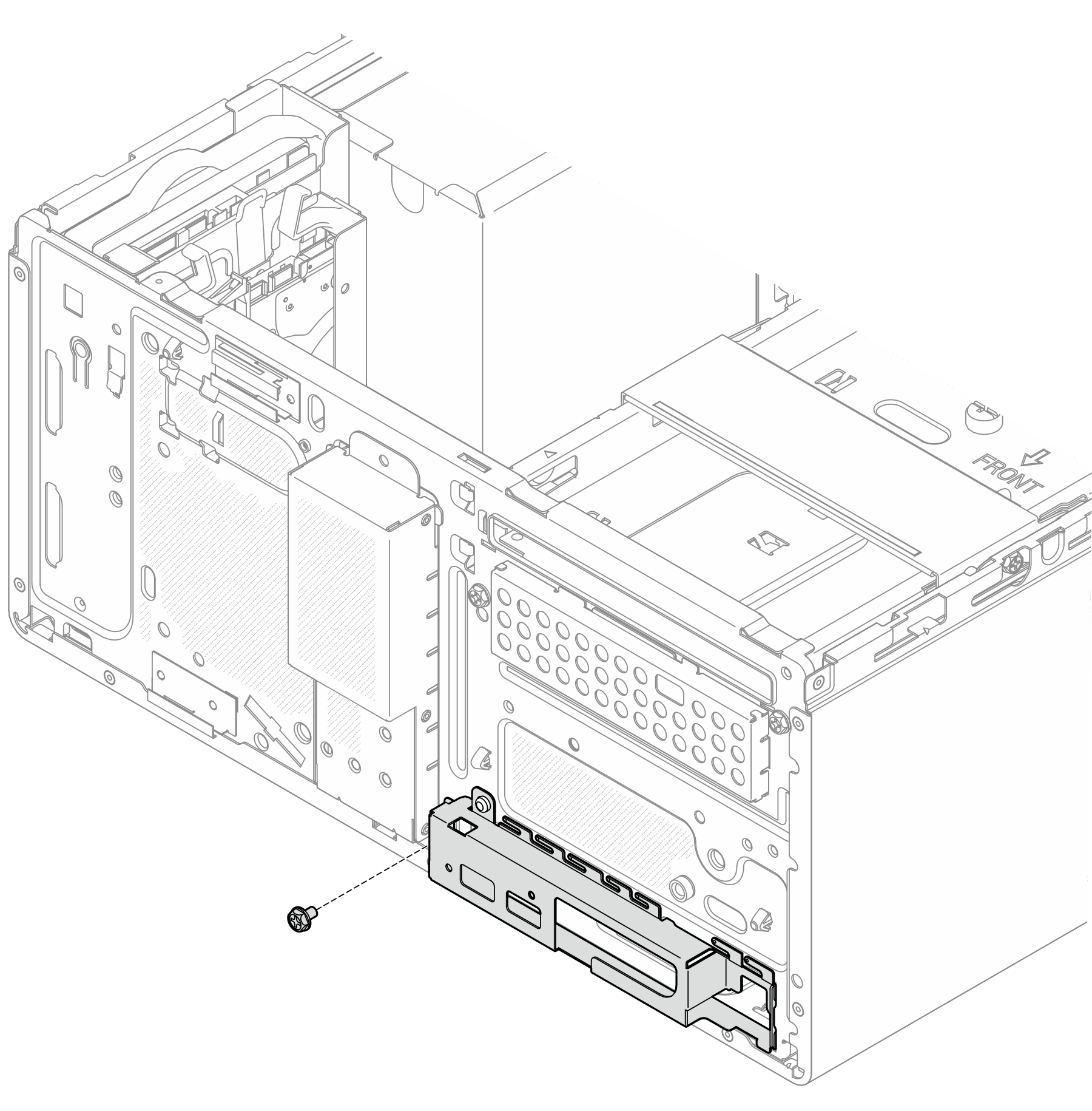
 Rotate the left end of the front I/O bracket away from the chassis.
 Remove the front I/O bracket from the chassis.Figure 2. Removing the front I/O bracket from the chassis
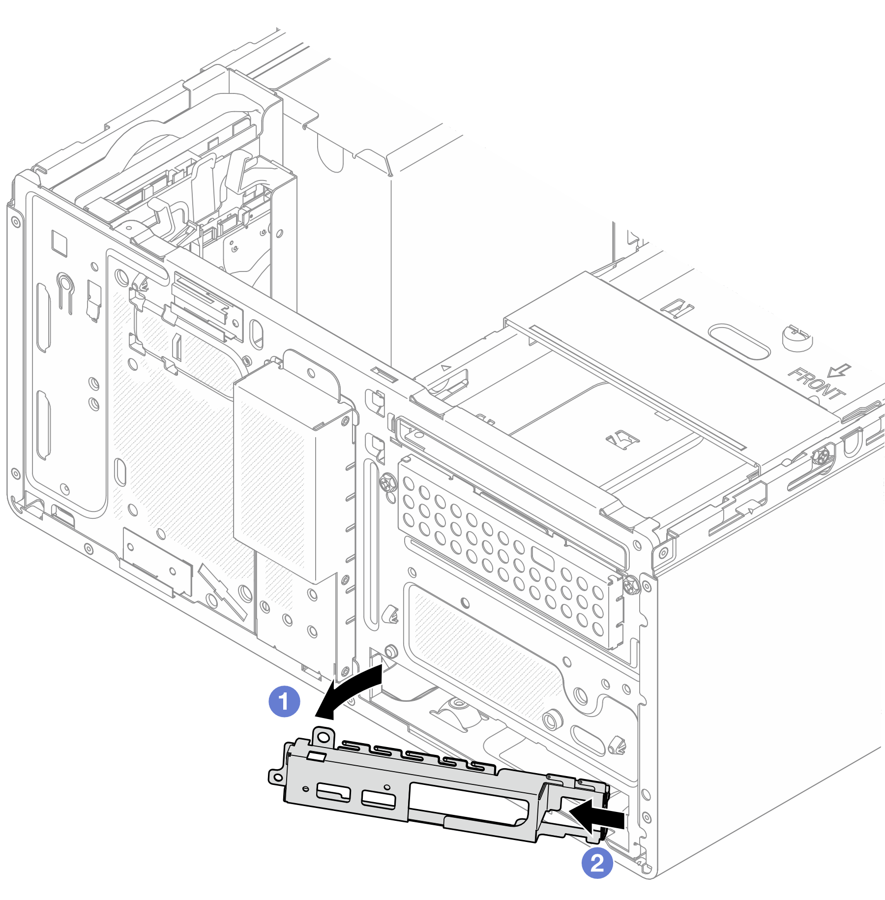
- Remove the screw the secures the front I/O bracket to the chassis.
- Remove the nine screws that secure the system board in the sequence shown on the illustration below. Keep the screws for future use.Figure 3. System-board screws removal sequence
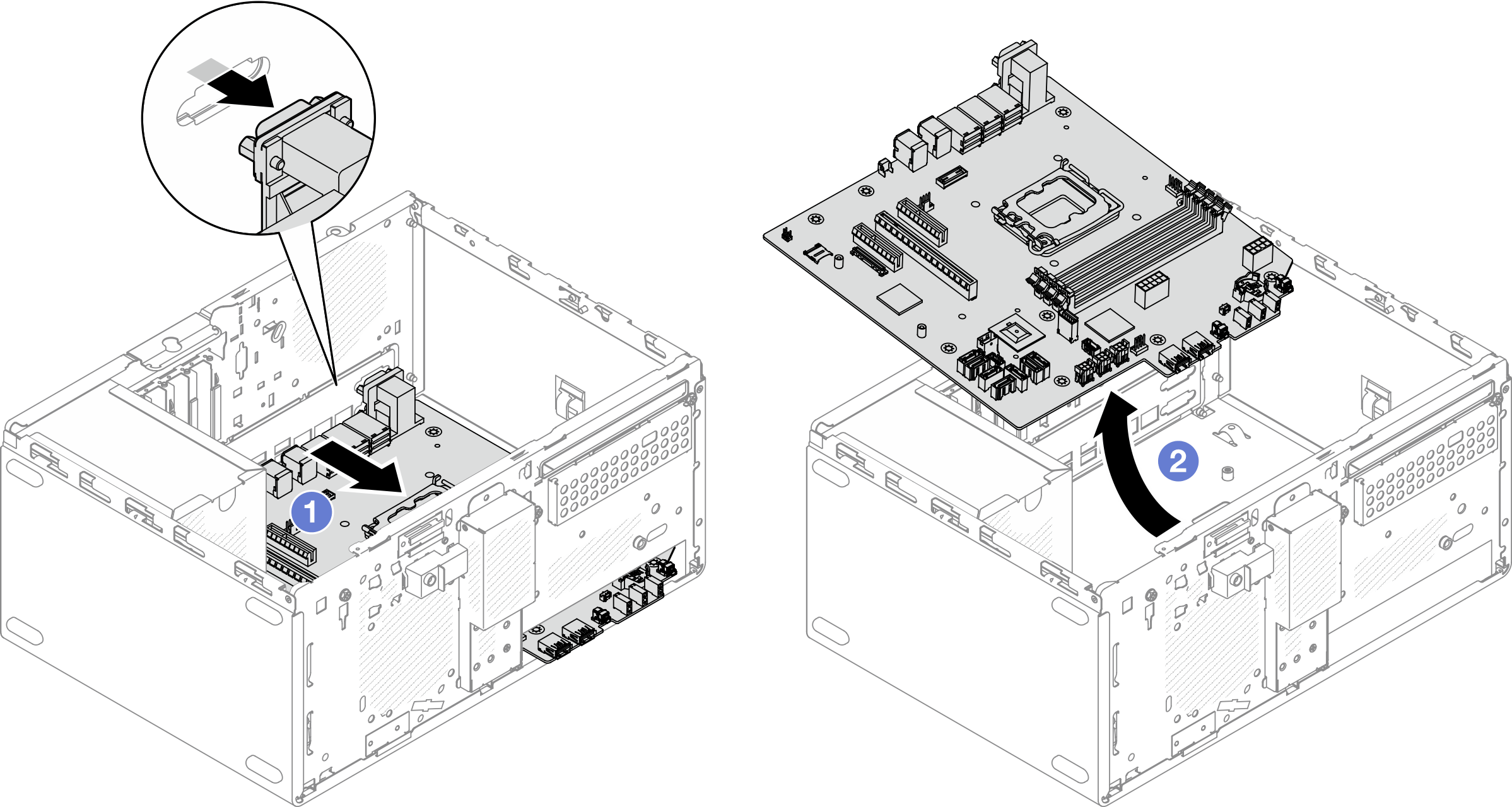
- Remove the system board from the chassis.
- Slide the system board toward the front of the server to release the serial port connector from the chassis.
- Gently grasp the system board by the edges; then, tilt the system board, and remove it from the chassis.Figure 4. Removing the system board from the chassis
After you finish
- If you are instructed to return the component or optional device, follow all packaging instructions, and use any packaging materials for shipping that are supplied to you.ImportantBefore you return the system board, make sure that you install the CPU socket covers from the new system board. To replace a CPU socket cover:
Take a socket cover from the CPU socket assembly on the new system board and orient it correctly above the CPU socket assembly on the removed system board.
Gently press down the socket cover legs to the CPU socket assembly, pressing on the edges to avoid damage to the socket pins. You might hear a click on the socket cover is securely attached.
Make sure that the socket cover is securely attached to the CPU socket assembly.
If you plan to recycle the component, see Disassemble the system board for recycle.
Demo video
Give documentation feedback