After updating the Lenovo TOR switch, ensure that the switch is fully functional, based on the solution configuration.
In addition to comparing the running configuration of the switch to the backup configuration file saved before updating the switch firmware, the following suggested validation procedures help to verify that:
Switch NOS is updated and set to boot to it
vLAG ISL is intact and operational
BGP connections are up and sessions are established
VRRP master and backup are up and forwarding
All links are up and IP addresses are assigned
ACLs are in place and counters are incrementing
Perform the following tasks to ensure that the updated TOR switch is working properly before proceeding. Use PuTTY on the HLH to connect to the TOR switch. Select
Yes in the PuTTY Security Alert that displays.
Figure 1. PuTTY security alert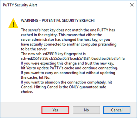
To verify that the Lenovo TOR switch NOS update has been applied, enter the following command:
| Example |
|---|
Lenovo-TOR1#show version
Lenovo Networking Operating System (NOS) Software
Technical Assistance Center: http://www.lenovo.com
Copyright (C) Lenovo, 2016.  All rights reserved.

Software:
  Bootloader version: 10.8.1.0
  System version: 10.8.1.0
  System compile time: Jul 18 17:06:53 PDT 2018
Hardware:
  NE2572 ("48x25GE + 6x100GE")
  Intel(R) Celeron(R) CPU with 8192 MB of memory

  Device name: Lenovo-TOR1
  Boot Flash: 16 MB

Kernel uptime is 0 day(s), 0 hour(s), 6 minute(s), 46 second(s)

Last Reset Reason: Power Cycle
Lenovo-TOR1#

2019-01-09T23:18:00.924+00:00 Lenovo-TOR1(cnos:default) %VLAG-5-OS_MISMATCH: vLAG OS version mismatch,
local OS version is 10.8.x.x peer OS version is 10.6.x.x
2019-01-09T23:18:10.924+00:00 Lenovo-TOR1(cnos:default) %VLAG-5-OS_MISMATCH: vLAG OS version mismatch,
local OS version is 10.8.x.x peer OS version is 10.6.x.x
|
You might see informational messages display periodically, as shown at the end of the example above, indicating an OS mismatch between the two TOR switches. This is expected at this point in the process. These messages should stop displaying after updating the second TOR switch.
To verify that the TOR switch is set to boot to the new firmware image (which is now the active image), enter the following command:
| Example |
|---|
Lenovo-TOR1#show boot
Current ZTP State: Enable
Current FLASH software:
  active image: version 10.8.1.0, downloaded 00:33:35 PST Thu Jan 10 2019
  standby image: version 10.6.1.0, downloaded 18:24:35 PST Fri Jan 12 2018
  Grub: version 10.8.1.0, downloaded 23:09:14 PST Wed Jan  9 2019
  BIOS: version 020AB, release date 02/14/2018
  Secure Boot: Enabled
  ONIE: version unknown, downloaded unknown
Currently set to boot software active image
Current port mode:
        Port Ethernet1/37 is set in 10G mode
        Port Ethernet1/38 is set in 10G mode
        Port Ethernet1/39 is set in 10G mode
        Port Ethernet1/40 is set in 10G mode
        Port Ethernet1/45 is set in 10G mode
        Port Ethernet1/46 is set in 10G mode
        Port Ethernet1/47 is set in 10G mode
        Port Ethernet1/48 is set in 10G mode
Next boot port mode:
        Port Ethernet1/37 is set in 10G mode
        Port Ethernet1/38 is set in 10G mode
        Port Ethernet1/39 is set in 10G mode
        Port Ethernet1/40 is set in 10G mode
        Port Ethernet1/45 is set in 10G mode
        Port Ethernet1/46 is set in 10G mode
        Port Ethernet1/47 is set in 10G mode
        Port Ethernet1/48 is set in 10G mode
Currently scheduled reboot time: none
|
To verify that all links are up and IP addresses are assigned, run the following command:
| show interface brief | include up |
| Example |
|---|
Lenovo-TOR1#show interface brief | include up
Ethernet1/1     7      eth  trunk  up      none             25000    --
Ethernet1/2     7      eth  trunk  up      none             25000    --
Ethernet1/3     7      eth  trunk  up      none             25000    --
Ethernet1/4     7      eth  trunk  up      none             25000    --
Ethernet1/40    --     eth  routed up      none             10000    --
Ethernet1/43    --     eth  routed up      none             25000    --
Ethernet1/44    --     eth  routed up      none             25000    --
Ethernet1/47    --     eth  routed up      none             10000    --
Ethernet1/48    --     eth  routed up      none             10000    --
Ethernet1/49    99     eth  trunk  up      none            100000   101
Ethernet1/50    99     eth  trunk  up      none            100000   101
po101           99     eth  trunk  up      none            100000  lacp
mgmt0  management   up     10.30.8.170                       1000  1500
Vlan7           --                 up     --
Vlan107         --                 up     --
loopback0           up         Loopback0_Rack1_TOR1
|
The state of Ethernet interfaces 1/5 through 1/16 depend on the number of nodes in the scale unit. The above example is taken from a 4-Node SXM4400 solution.
To verify that the vLAG ISL is intact and operational, run the following command:
| Example |
|---|
Lenovo-TOR1#show vlag information
  Global State:            enabled
  VRRP active/active mode: enabled
  vLAG system MAC:         08:17:f4:c3:dd:63
  ISL Information:
    PCH     Ifindex     State       Previous State
    -------+-----------+-----------+---------------------------------
    101     100101      Active      Inactive

  Mis-Match Information:
                   Local                      Peer
    -------------+---------------------------+-----------------------
    Match Result : Match                      Match
    Tier ID      : 100                        100
    System Type  : NE2572                     NE2572
    OS Version   : 10.8.x.x                   10.8.x.x

  Role Information:
                   Local                      Peer
    -------------+---------------------------+-----------------------
    Admin Role   : Primary                    Secondary
    Oper Role    : Secondary                  Primary
    Priority     : 0                          0
    System MAC   : a4:8c:db:bb:0b:01          a4:8c:db:bb:0c:01

  Consistency Checking Information:
    State             : enabled
    Strict Mode       : disabled
    Final Result      : pass
|
To verify that the BGP connections are up and sessions are established, run the following command:
| Example |
|---|
Lenovo-TOR1#show ip bgp summary
BGP router identifier 10.30.8.152, local AS number 64675
BGP table version is 74
2 BGP AS-PATH entries
0 BGP community entries
8  Configured ebgp ECMP multipath: Currently set at 8
8  Configured ibgp ECMP multipath: Currently set at 8

Neighbor       V     AS MsgRcv MsgSen TblVer InQ OutQ Up/Down State/PfxRcd
10.30.8.146    4  64675    72     74     74    0    0 01:09:14       5
10.30.8.158    4  64675    74     74     74    0    0 01:09:15      33
10.30.8.162    4  64675    74     74     74    0    0 01:09:24      33
10.30.29.12    4  64719   235    215     74    0    0 01:09:17      25
10.30.29.13    4  64719   235    214     74    0    0 01:09:17      25

Total number of neighbors 5

Total number of Established sessions 5
|
Note that the above example is from a statically routed solution. A solution using dynamic routing also includes two BGP sessions for the Border switches, totaling 7 sessions.
To verify that the VRRP master and backup are up and forwarding, run the following command on each TOR switch:
| Example |
|---|
Lenovo-TOR1#show vrrp vlag
   Flags: F - Forwarding enabled on Backup for vLAG
   vLAG enabled, mode: vrrp active
   Interface     VR  IpVer Pri Time    Pre  State   VR IP addr
------------------------------------------------------------------
(F)Vlan7         7   IPV4  100 100  cs  Y   Backup  10.30.29.1
(F)Vlan107       107 IPV4  100 100  cs  Y   Backup  10.30.28.1


Lenovo-TOR2#show vrrp vlag
   Flags: F - Forwarding enabled on Backup for vLAG
   vLAG enabled, mode: vrrp active
   Interface     VR  IpVer Pri Time    Pre  State   VR IP addr
------------------------------------------------------------------
   Vlan7         7   IPV4  100 100  cs  Y   Master  10.30.29.1
   Vlan107       107 IPV4  100 100  cs  Y   Master  10.30.28.1
|
To verify that ACLs are in place and counters are incrementing, run the following commands:
| show ip access-lists summaryshow ip access-lists |
| Example |
|---|
Lenovo-TOR-1#show ip access-lists summary
IPV4 ACL Rack01-CL01-SU01-Infra_IN
        statistics enabled
        Total ACEs Configured: 28
        Configured on interfaces:
                Vlan7 - ingress (Router ACL)
        Active on interfaces:
                Vlan7 - ingress (Router ACL)
        Configured and active on VRFs:
IPV4 ACL Rack01-CL01-SU01-Infra_OUT
        statistics enabled
        Total ACEs Configured: 28
        Configured on interfaces:
                Vlan7 - egress (Router ACL)
        Active on interfaces:
                Vlan7 - egress (Router ACL)
        Configured and active on VRFs:
IPV4 ACL Rack01-CL01-SU01-Stor_IN
        statistics enabled
        Total ACEs Configured: 6
        Configured on interfaces:
                Vlan107 - ingress (Router ACL)
        Active on interfaces:
                Vlan107 - ingress (Router ACL)
        Configured and active on VRFs:
IPV4 ACL Rack01-CL01-SU01-Stor_OUT
        statistics enabled
        Total ACEs Configured: 6
        Configured on interfaces:
                Vlan107 - egress (Router ACL)
        Active on interfaces:
                Vlan107 - egress (Router ACL)
        Configured and active on VRFs:
IPV4 ACL UPLINK_ROUTED_IN
        statistics enabled
        Total ACEs Configured: 4
        Configured on interfaces:
                Ethernet1/47 - ingress (Router ACL)
                Ethernet1/48 - ingress (Router ACL)
        Active on interfaces:
                Ethernet1/47 - ingress (Router ACL)
        Configured and active on VRFs:
IPV4 ACL copp-system-acl-authentication
        Total ACEs Configured: 3
        Configured on interfaces:
        Active on interfaces:
        Configured and active on VRFs:
IPV4 ACL copp-system-acl-bgp
        Total ACEs Configured: 2
        Configured on interfaces:
        Active on interfaces:
        Configured and active on VRFs:
...
|
| Example |
|---|
Lenovo-TOR-1#show ip access-lists
IP access list  Rack01-CL01-SU01-Infra_IN
        statistics per-entry
        500 remark "Permit R01-C01-SU01-INF (10.20.25.0/24)_TO_R01-C01-SU01-INF
(10.20.25.0/24)"
        510 permit any 10.20.25.0/24 10.20.25.0/24 [match=70214264]
        520 remark "Permit R01-C01-SU01-INF (10.20.25.0/24)_TO_azs-hlh-dvm00 (10
.20.3.61/32)"
        530 permit any 10.20.25.0/24 host 10.20.3.61 [match=11180]
        540 remark "Permit R01-C01-SU01-INF (10.20.25.0/24)_TO_R01-C01-SU01-InVI
P (10.20.126.128/25)"
        550 permit any 10.20.25.0/24 10.20.126.128/25
        560 remark "Permit R01-C01-SU01-InVIP (10.20.126.128/25)_TO_R01-C01-SU01
-INF (10.20.25.0/24)"
        570 permit any 10.20.126.128/25 10.20.25.0/24 [match=27814360]
        580 remark "Permit R01-C01-SU01-INF (10.20.25.0/24)_TO_pub-adm-vip (10.2
0.23.0/27)"
        590 permit any 10.20.25.0/24 10.20.23.0/27 [match=80158]
        600 remark "Permit pub-adm-vip (10.20.23.0/27)_TO_R01-C01-SU01-INF (10.2
0.25.0/24)"
        610 permit any 10.20.23.0/27 10.20.25.0/24 [match=76824]
        620 remark "Permit 112 any (0.0.0.0/0)_to_Multicast (224.0.0.18/32)"
        630 permit 112 any host 224.0.0.18 [match=62576]
        640 remark "Permit UDP any_TO_any(BOOTP) port 67"
        650 permit udp any any eq bootps [match=443]
...
|
Once the basic system convergence is verified in the updated Lenovo TOR switch, test solution connectivity using the following steps:
Use the top menu of the XClarity Administrator browser interface to navigate to .
Click the Test Connection button near the top of the interface.
In the Host field, enter 8.8.8.8, and click Test Connection.
A success window displays. Click Close to dismiss this window.
As an additional verification step, sign in to the Azure Stack Hub Administrator Portal.
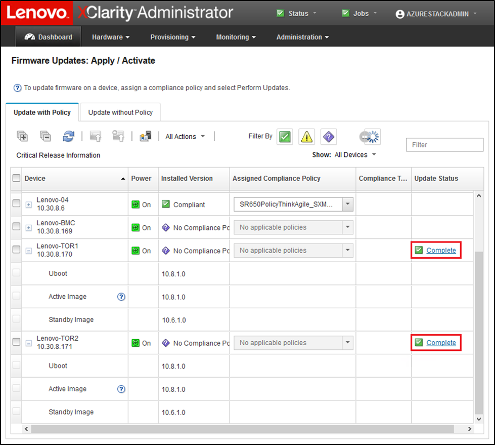
Check the Azure Stack Hub Administrator Portal Portal to ensure that no alerts are currently visible.
Figure 2. Checking Azure Stack Hub Administrator Portal for alerts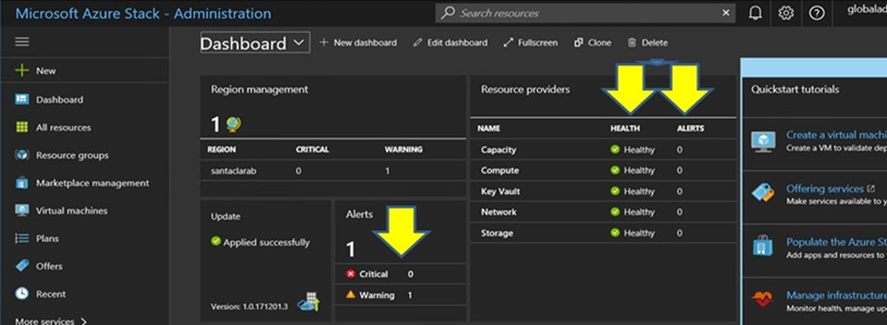
Wait until network traffic and reachability fully reconverge and the systems stabilize. Also check the Azure Stack Hub Administrator Portal to ensure all component status indicators are shown as healthy. Once the solution has stabilized, return to the “Update CNOS on TOR switches” topic and repeat the process on the other TOR switch. Once both TOR switches have been updated and their functionality and stability have been verified, proceed with the BMC switch update.
Figure 3. Verifying that TOR switch firmware updates are complete