Installing 2 x 8 1.8-inch SSDs with two 6 GB performance optimized HBA adapters option
Use this information to install 2 x 8 1.8-inch SSDs with two 6 GB performance optimized HBA adapters option.
To order 2 x 8 1.8-inch SSDs with two 6 GB performance optimized HBA adapters option, contact your sales representative or reseller.
The 2 x 8 1.8-inch SSDs with two 6 GB performance optimized HBA adapters option kit contains the following components:
- Four SAS signal cables
- Two configuration cables
- One internal power cable
- Two eXFlash 1.8-inch drive cage and backplane assemblies
- Two RAID adapters (part number 46M0912)NoteRAID adapters come in a different option kits. Touch the static-protective packages to any unpainted metal surface on the server.
To install the 2 x 8 1.8-inch SSDs with two 6 GB performance optimized HBA adapters option in the server, complete the following steps.
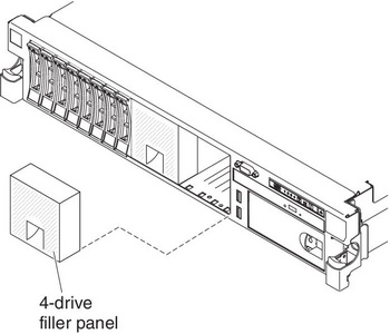
- Remove the two 4-drive filler panels that are to the right of drive bay 8, beneath the IDs 8 - 15 on the front bezel.Figure 1. Filler panels
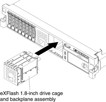
- Install the new backplane assemblies.Figure 2. New backplane assemblies installation
- Connect the following cables in the order listed:
- Configuration cable 1
- SAS signal cables 2
- Power cable 3
Figure 3. Cable connections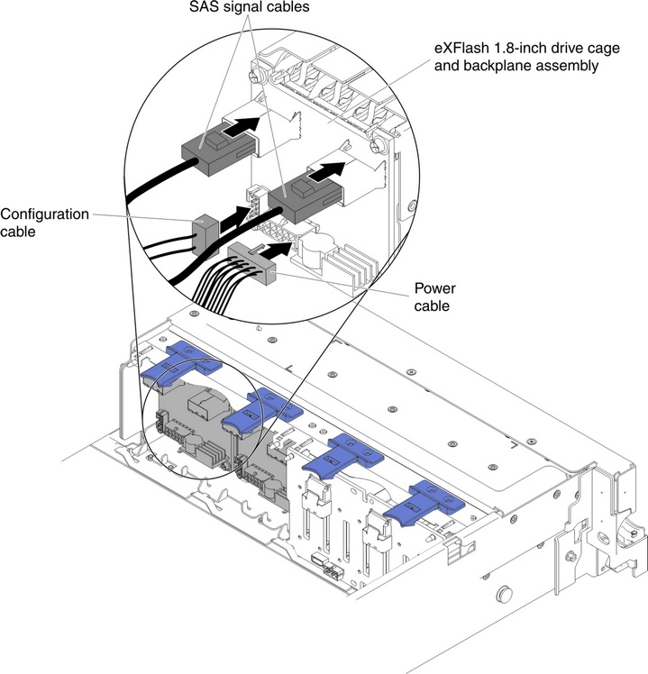
- Connect the SAS signal cables to the connectors on the RAID adapter:
- Connect another SAS signal cable to the other SAS connector for drive bays 12-15.Figure 4. RAID adapter connectors

- Connect another SAS signal cable to the other SAS connector for drive bays 12-15.
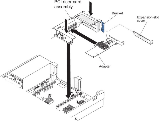
- Align and install the PCI riser-card assembly 1 in the server (see Installing a PCI riser-card assembly).Figure 5. PCI riser-card assembly installation
- Route the cables underneath the cable retention.Figure 6. SAS signal cables routing
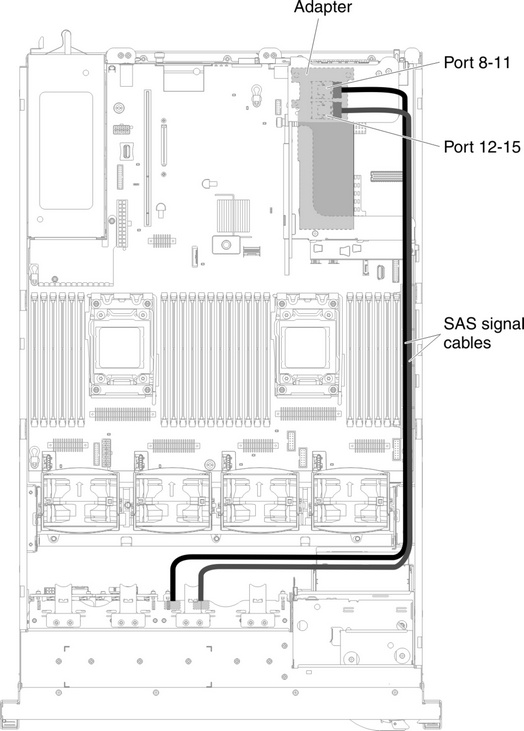 Figure 7. SAS signal cables routing
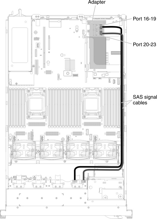
- Make sure that the configuration cable is connected to the backplanes and system board.Figure 8. Configuration cables routing
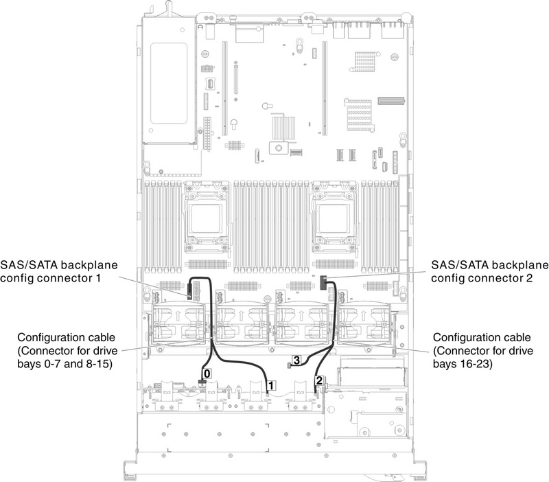 NoteLeave the cable segment with the label 3 unconnected.
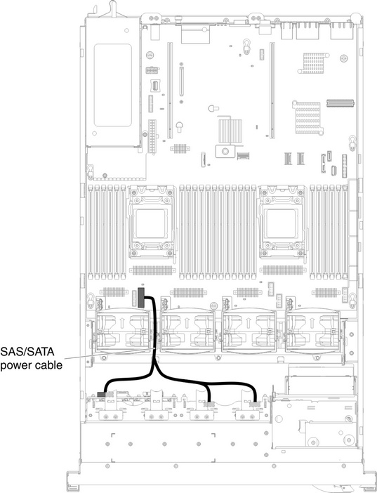
 - Make sure that the SAS power cable is connected to the backplanes and system board.Figure 9. SAS/SATA power cable routing
If you have other devices to install or remove, do so now. Otherwise, go to Completing the installation.
Give documentation feedback