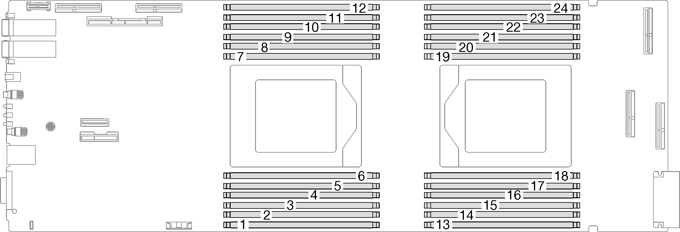
Install a memory module
Use this information to install a memory module.
About this task
See Memory module installation rules and order for detailed information about memory configuration and setup.
When removing/installing the memory module, do not tilt the memory module and keep it at an upright position to prevent damaging the gap pad.
Read Installation Guidelines and Safety inspection checklist to ensure that you work safely.
Make sure to remove or install memory module 20 seconds after disconnecting power cords from the system. It allows the system to be completely discharged of electricity and safe for handling memory module.
- Memory modules are sensitive to static discharge and require special handling. In addition to the standard guidelines for Handling static-sensitive devices:
Always wear an electrostatic-discharge strap when removing or installing memory modules. Electrostatic-discharge gloves can also be used.
Never hold two or more memory modules together so that they touch. Do not stack memory modules directly on top of each other during storage.
Never touch the gold memory module connector contacts or allow these contacts to touch the outside of the memory-module connector housing.
Handle memory modules with care: never bend, twist, or drop a memory module.
Do not use any metal tools (such as jigs or clamps) to handle the memory modules, because the rigid metals may damage the memory modules.
Do not insert memory modules while holding packages or passive components, which can cause package cracks or detachment of passive components by the high insertion force.
DIMM fillers must be installed in unused slots for proper cooling.
Before installing 24 Gb DRAM RDIMMs, make sure to update the UEFI firmware to the latest version first, then remove all existing 16 Gb DRAM RDIMMs.
Go to Drivers and Software download website for ThinkSystem SD665 V3 to see the latest firmware and driver updates for your server.
Go to Update the firmware for more information on firmware updating tools.
Procedure
Make sure to remove or install memory module 20 seconds after disconnecting power cords from the system. It allows the system to be completely discharged of electricity and safe for handling memory module.
Depending on the model, your solution might look slightly different from the illustration.
- Remove the memory module tool attached to the DIMM comb.Figure 2. Memory module tool removal
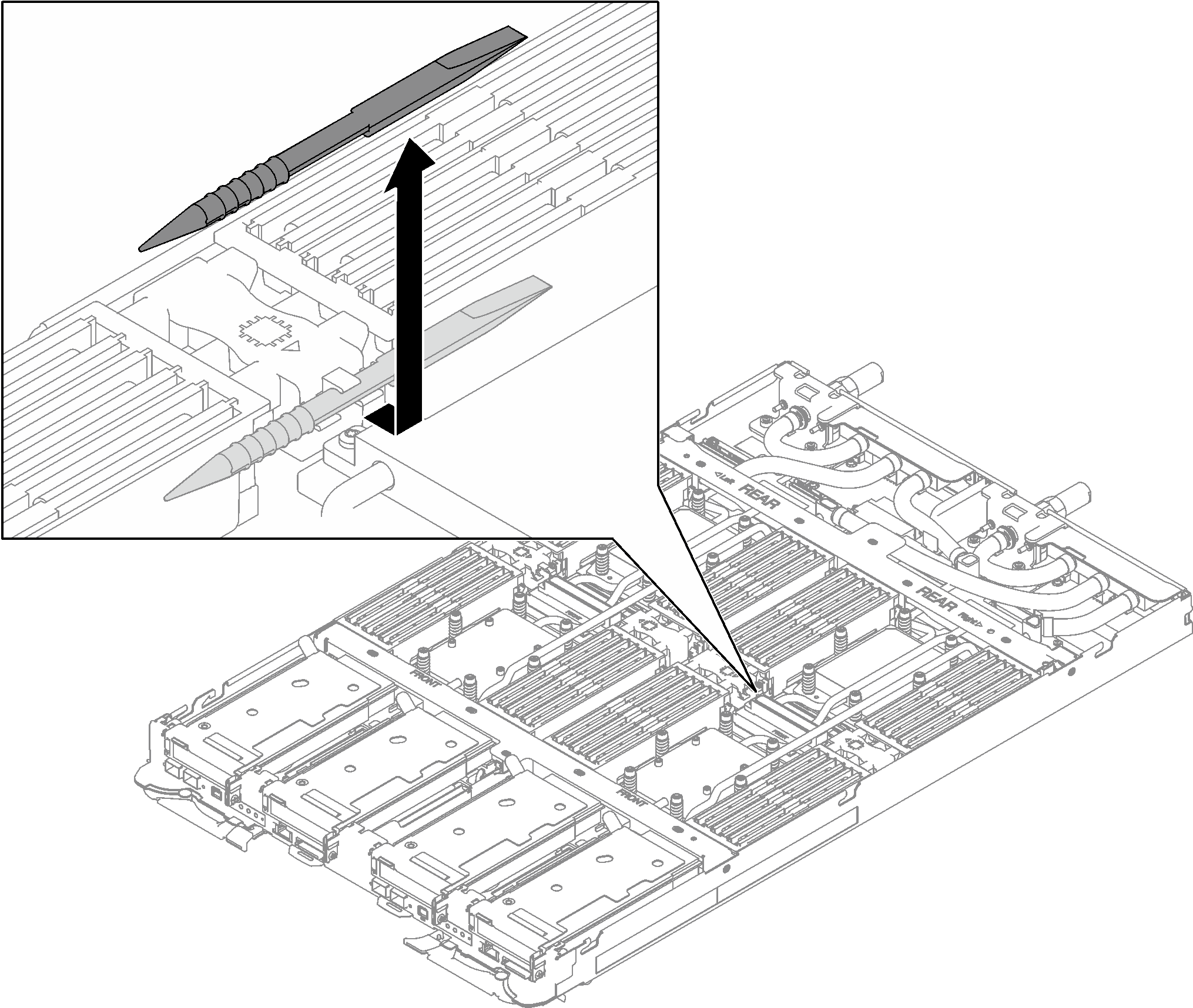 NoteMemory module tool is recommended due to space limitations caused by location of water loop tubes through the memory section.
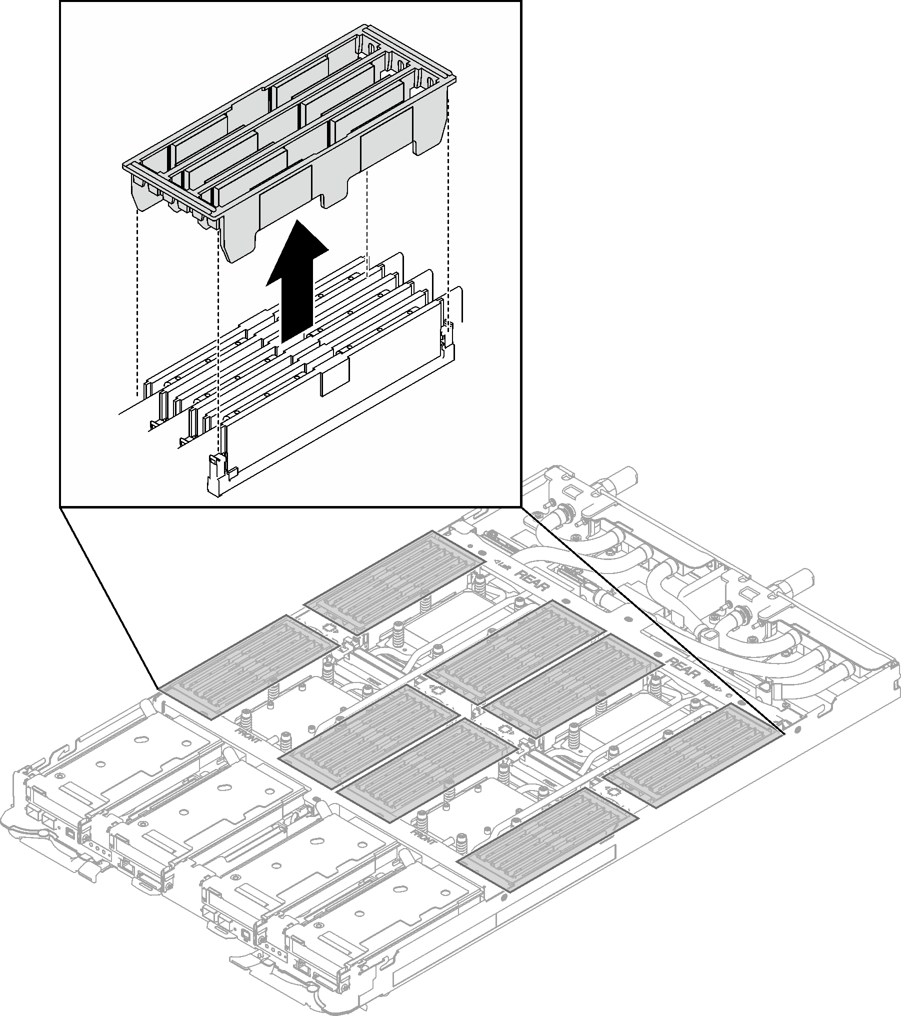
 - Remove the DIMM cover.NoteDo not tilt the DIMM cover and keep it at an upright position to prevent damaging the gap pads.Figure 3. DIMM cover removal
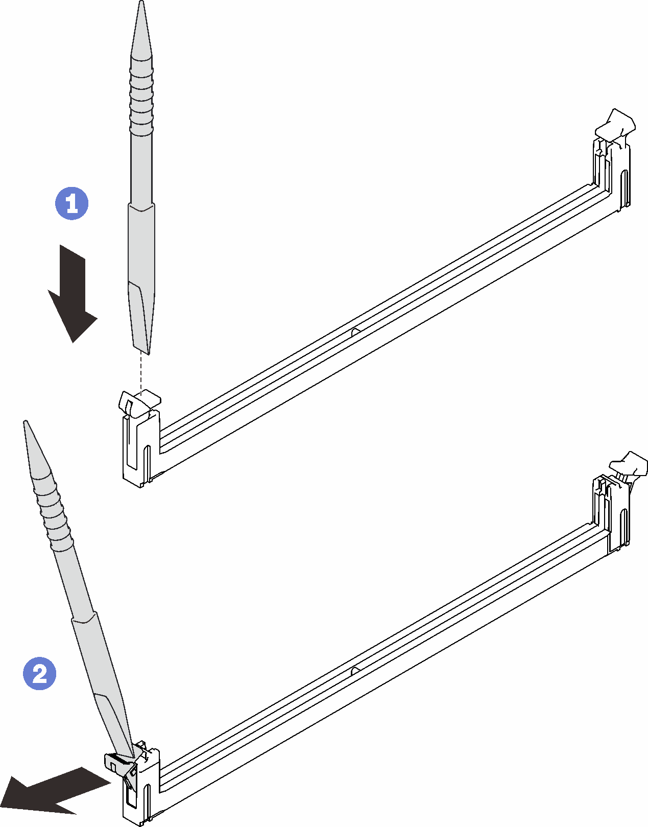
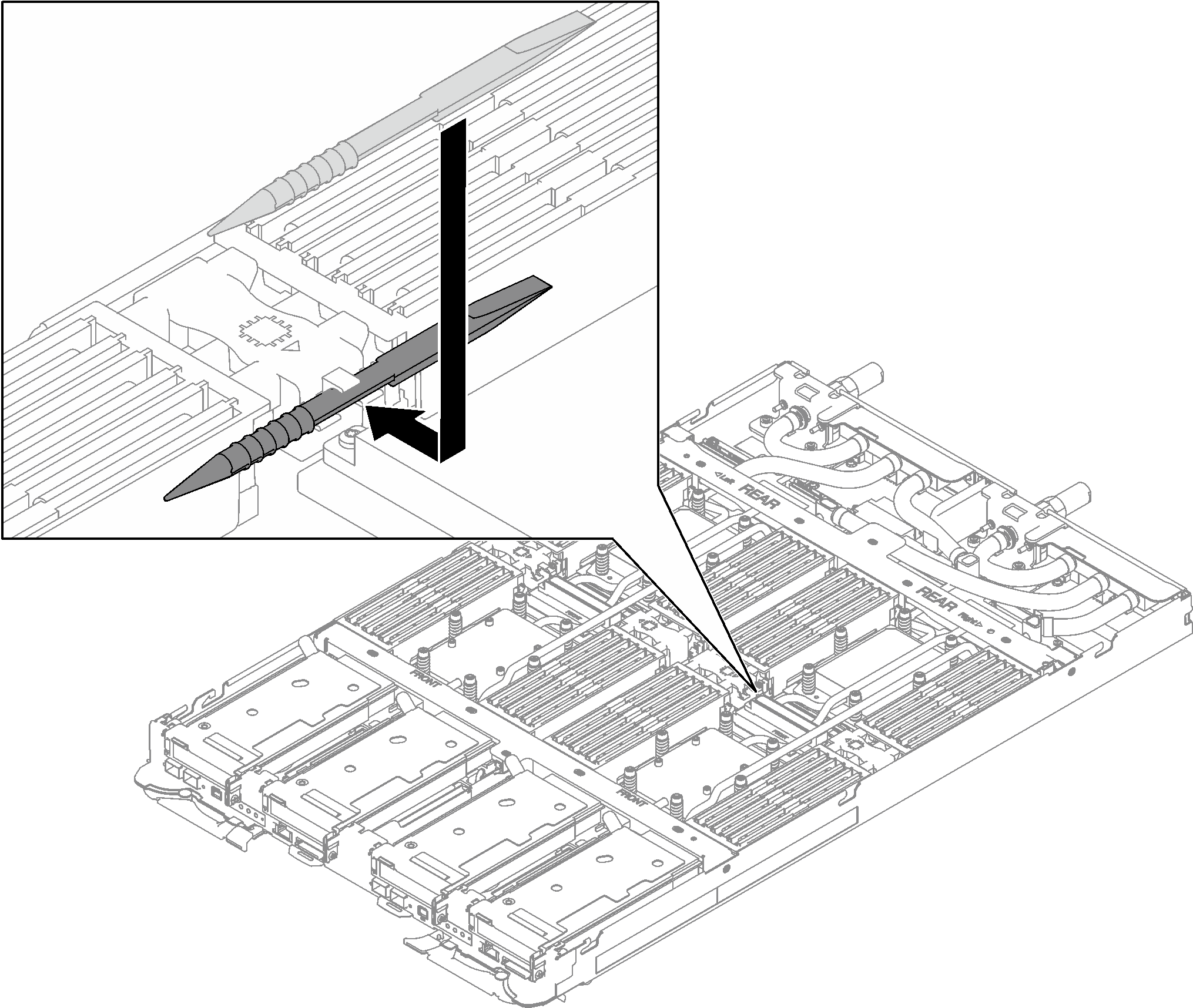
- Carefully use the memory module tool to press the retaining clips outward on each end of the memory module connector.Figure 4. Pressing retaining clips on memory module connector
 Attention
Memory modules are static-sensitive devices. The package must be grounded before it is opened.
To avoid breaking the retaining clips or damaging the memory module connectors, open and close the clips gently.
- Firmly press both ends of the memory module straight down into the slot until the retaining clips snap into the locked position.Attention
When removing/installing the memory module, do not tilt the memory module and keep it at an upright position to prevent damaging the gap pad.
Figure 5. Memory module installation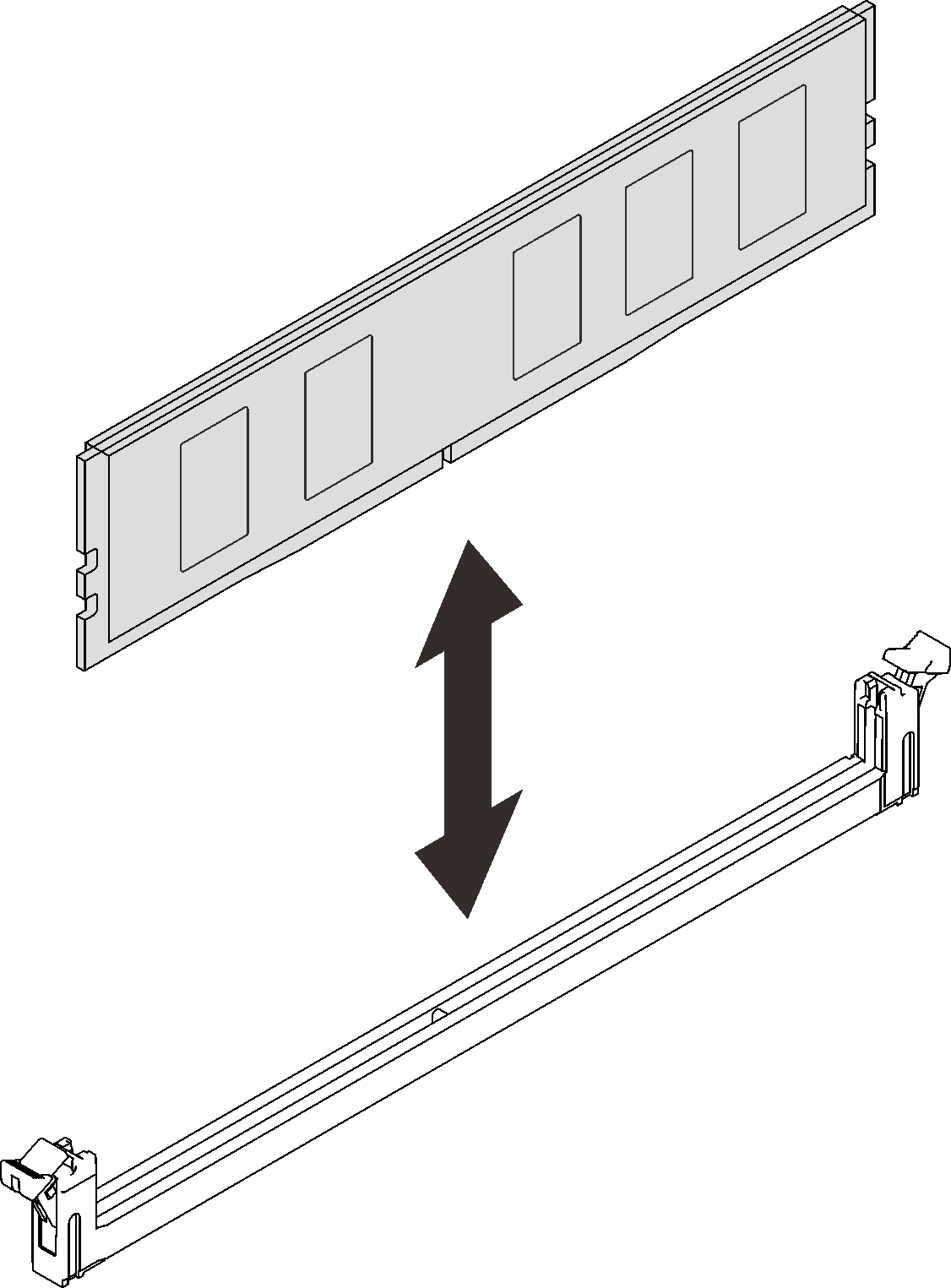 NoteIf there is a gap between the memory module and the retaining clips, the memory module has not been correctly inserted; open the retaining clips, remove the memory module, and then reinsert it.
 - Install the DIMM cover.NoteDo not tilt the DIMM cover and keep it at an upright position to prevent damaging the gap pads.Figure 6. DIMM cover installation
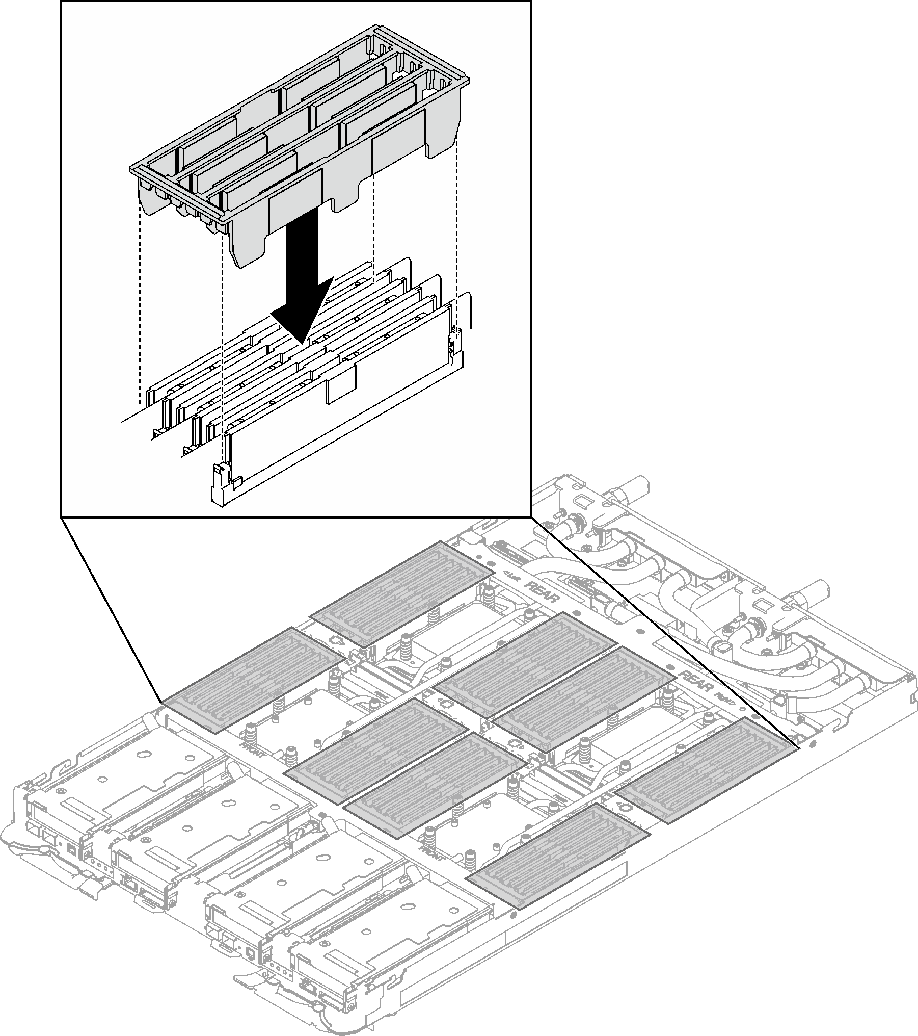 Note
NoteIf the DIMM cover is attached with rubber, as type A and type B shown below, the types of DIMM cover and the installation orientation is different depending on the DIMMs to be covered. Make sure to follow the rubber-attached DIMM cover mapping illustration below.
Figure 7. Rubber-attached DIMM cover type A and Type B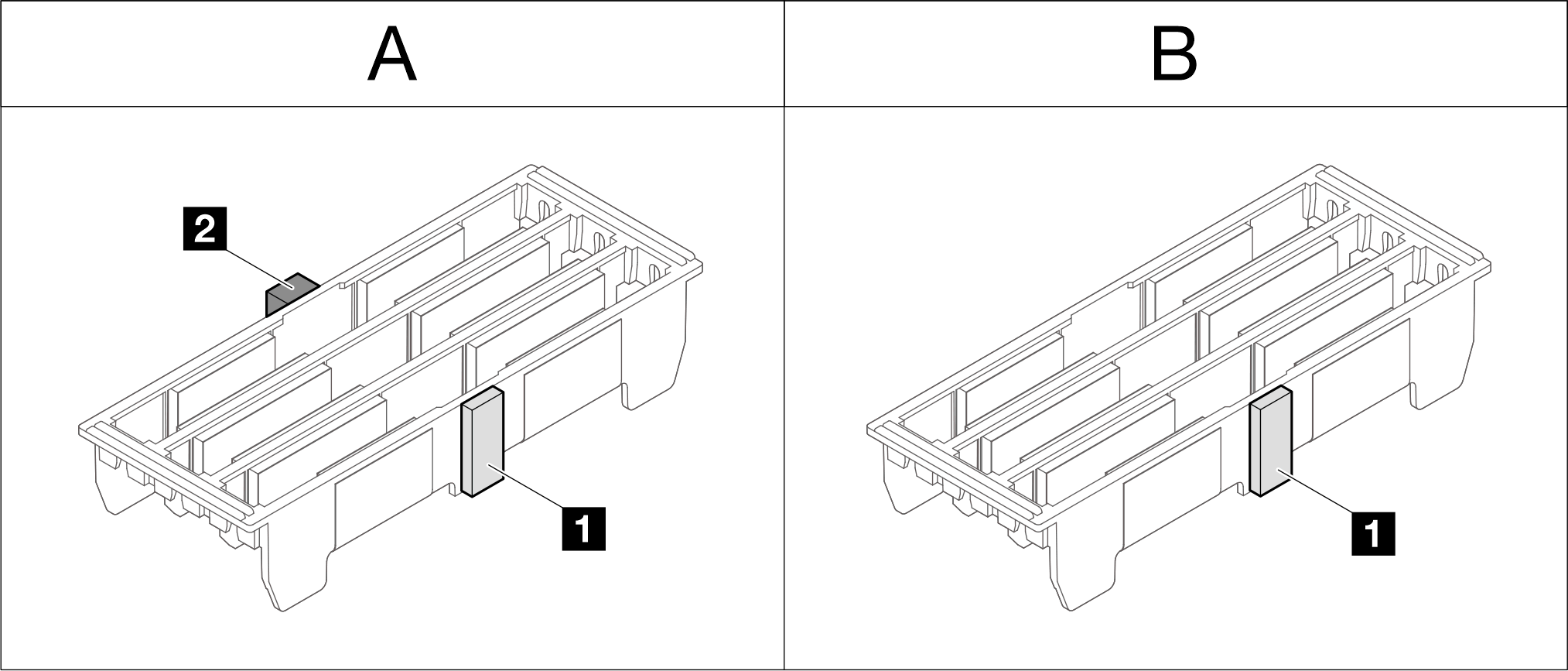
DIMM cover type Rubber(s) attached Installation orientation A 1 and 2.
1 is thinner than 2
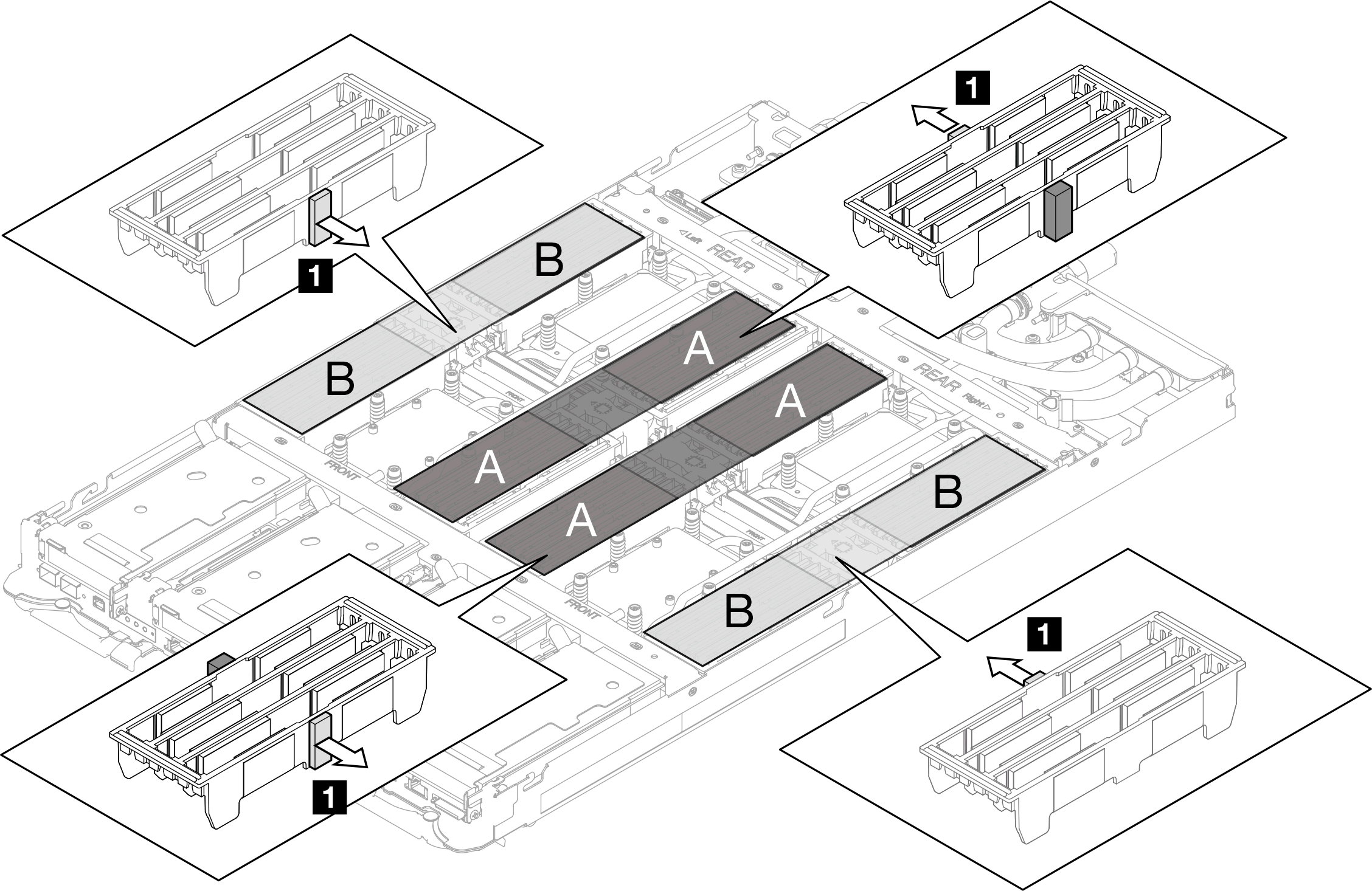
Rubber 1 should face the CPU when installing the DIMM cover. B 1 Figure 8. Rubber-attached DIMM cover mappingArea A: DIMMs to be covered by DIMM cover A
Area B: DIMMs to be covered by DIMM cover B
1: Thinner rubber should be facing the CPU side.
- Install the memory module tool to the DIMM comb on the left side of the node.Figure 9. Memory module tool installation
Install the tray cover. See Install the tray cover.
Install the tray into the enclosure. See Install a DWC tray in the enclosure.
- Connect all required external cables to the solution.NoteUse extra force to connect QSFP cables to the solution.
Check the power LED on each node to make sure it changes from fast blink to slow blink to indicate all nodes are ready to be powered on.
Demo video