Install a node to the rack
Follow instructions in this section to install a node to the rack.
About this task

Read Installation Guidelines and Safety inspection checklist to ensure that you work safely.
Power off the server and peripheral devices and disconnect the power cords and all external cables. See Power off the server.
Install the enclosure to the rack
Procedure
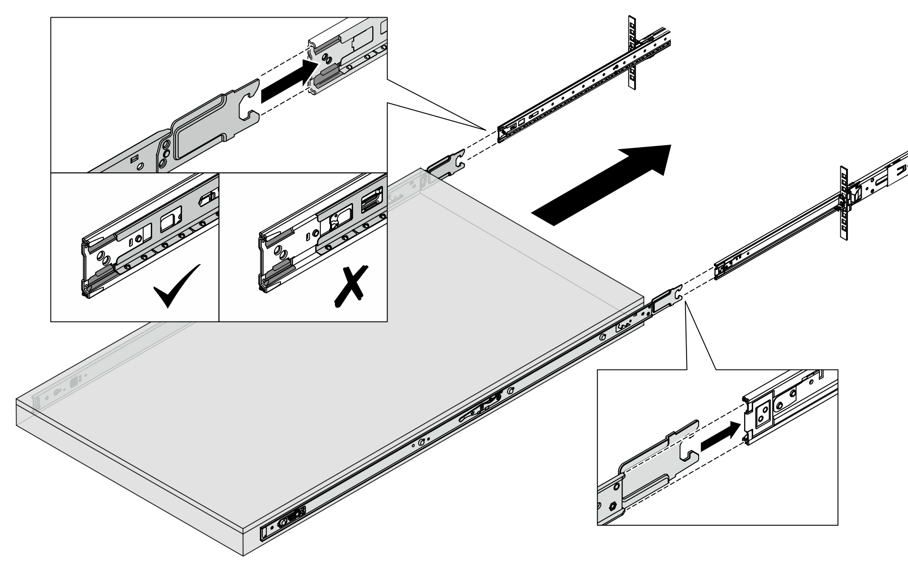
- Remove the inner rails from the intermediate rails.Figure 1. Removing the inner rails
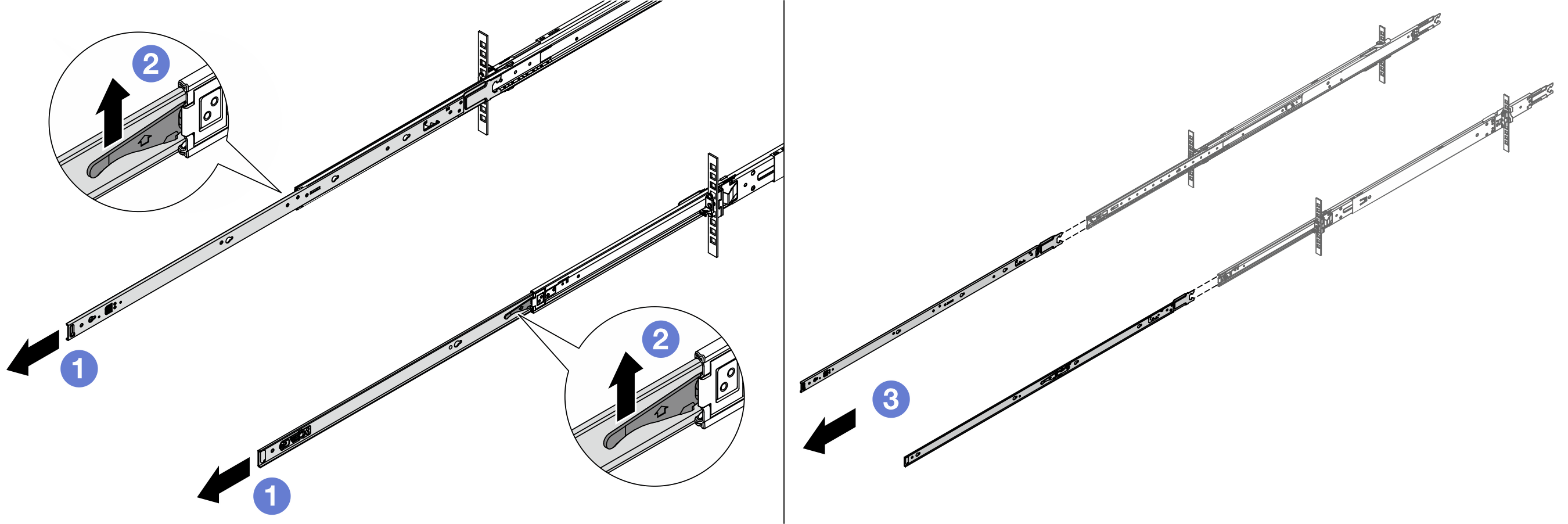
 Extend the inner rails.
 Push up the latches to disengage inner rails from the intermediate ones.
 Remove the inner rails.
- Align the slots on the inner rail with the corresponding T-pins on the side of the enclosure; then, slide the inner rail forwards until the T-pins lock into place.Note
Make sure that the stamp “Front” always face toward the front when assembling the inner rails to the enclosure.
“L” and “R” stamps indicate the left and right sides of the rails.
Figure 2. Installing an inner rail to the enclosure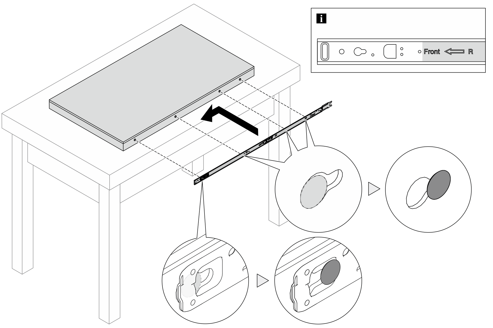
- Install the enclosure to the rack. Align both rear ends of the inner rails with the openings in the intermediate rails, and make sure that the two pairs of rails mate correctly.NoteBefore installing the inner rails to the intermediate ones, make sure that the ball retainers on both sides reach the outmost position. If the retainers are not in good position, slide them to the front until they stop.Figure 3. Installing the enclosure
- Lift the lock latches to proceed to slide the enclosure in.Figure 4. Locking latches
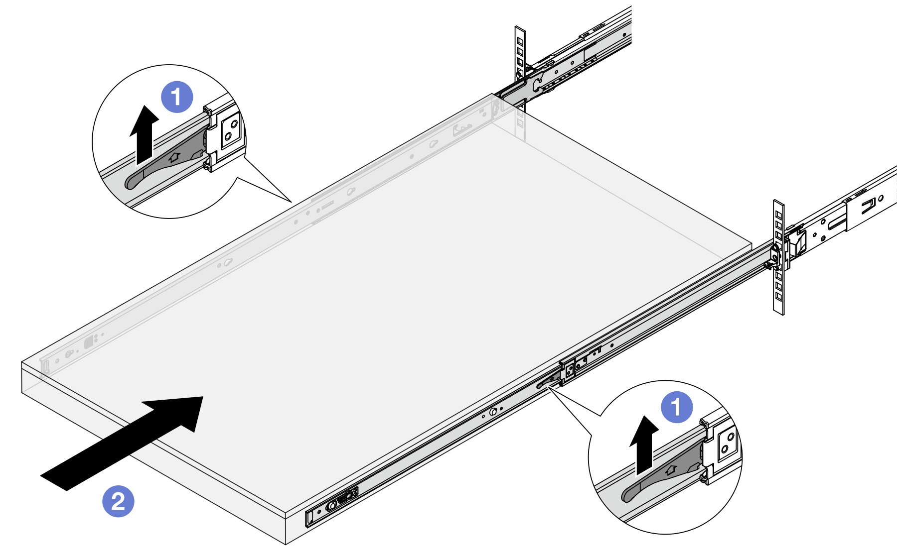
- Lift the lock latches on both sides.
- Push the enclosure all the way into the rack until both latches lock into position with a click.
- Secure the enclosure to the rack.
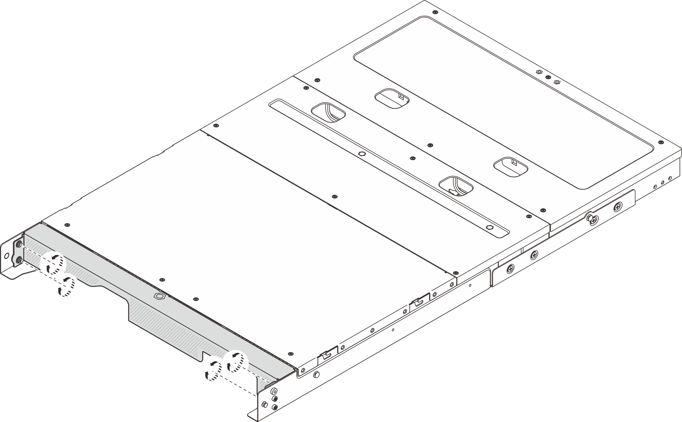
- Secure the enclosure to the front of the rack. Fasten the two screws located on the rack latches.Figure 5. Securing the enclosure to the front of the rack
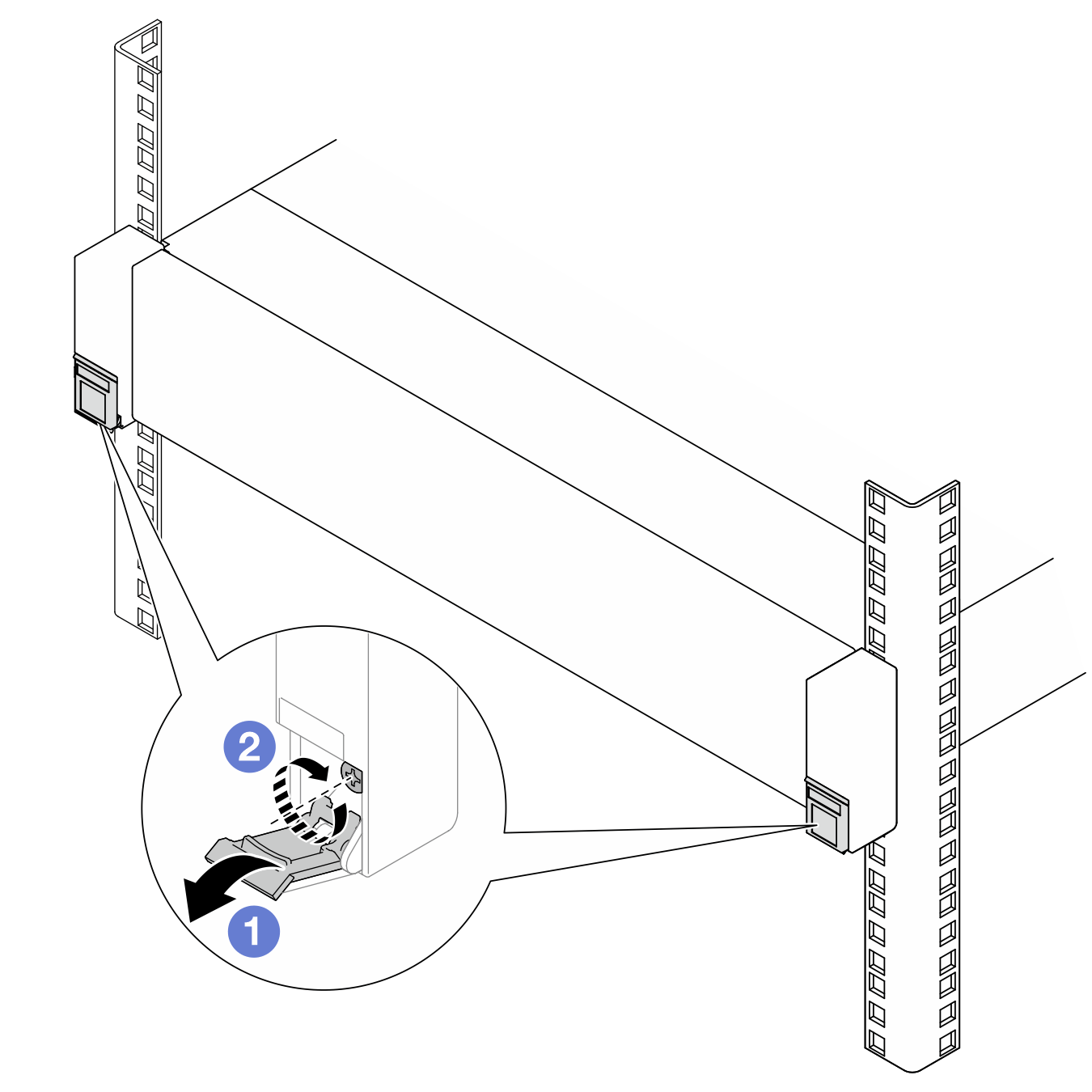
- Flip down the covers on the rack latches.
- Tighten the screws to secure the enclosure.
- (Optional) If the rack is shipped with enclosures or placed in a vibration-prone area, install one M6 screw to each of the rails to secure the enclosure to the rear of the rack.Figure 6. Securing the enclosure to the rear of the rack

- Secure the enclosure to the front of the rack. Fasten the two screws located on the rack latches.
Install the node to the enclosure
Procedure
- If a node filler is installed in the node bay, remove it first.
- Loosen the two screws that secure the node filler.
- Remove the node filler from the node bay. Keep the node filler in a safe place for future use.
Figure 7. Removing the node filler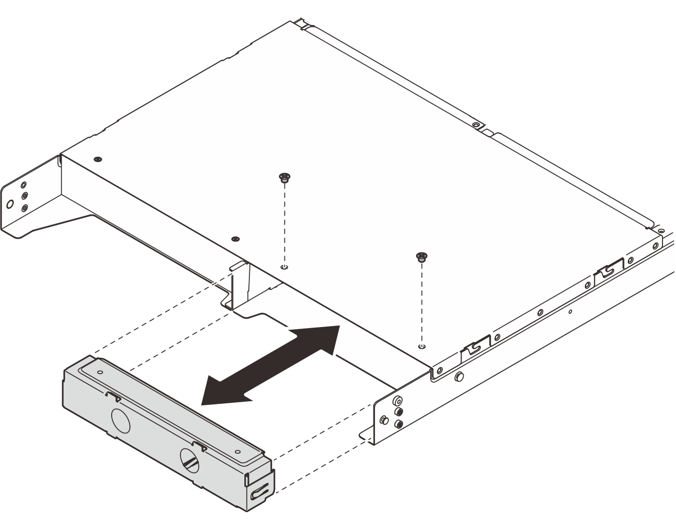
- Install the node into the node bay.ImportantWhen installing the node into the enclosure, do not press the enclosure top cover down.
Install the node to 1U2N Enclosure Bay 1 / 1U3N Enclosure Bay 1, Bay 2
- Hold the node with both hands. Put the rear left corner of node onto location of enclosure. Make sure the node bottom is above the bottom of enclosure.
- Slightly move the node forward, and slide the rear right corner of node into the bracket . Be careful to insert both top and bottom of the rear right corner into the bracket as shown in the illustration.Figure 8. Installing the node
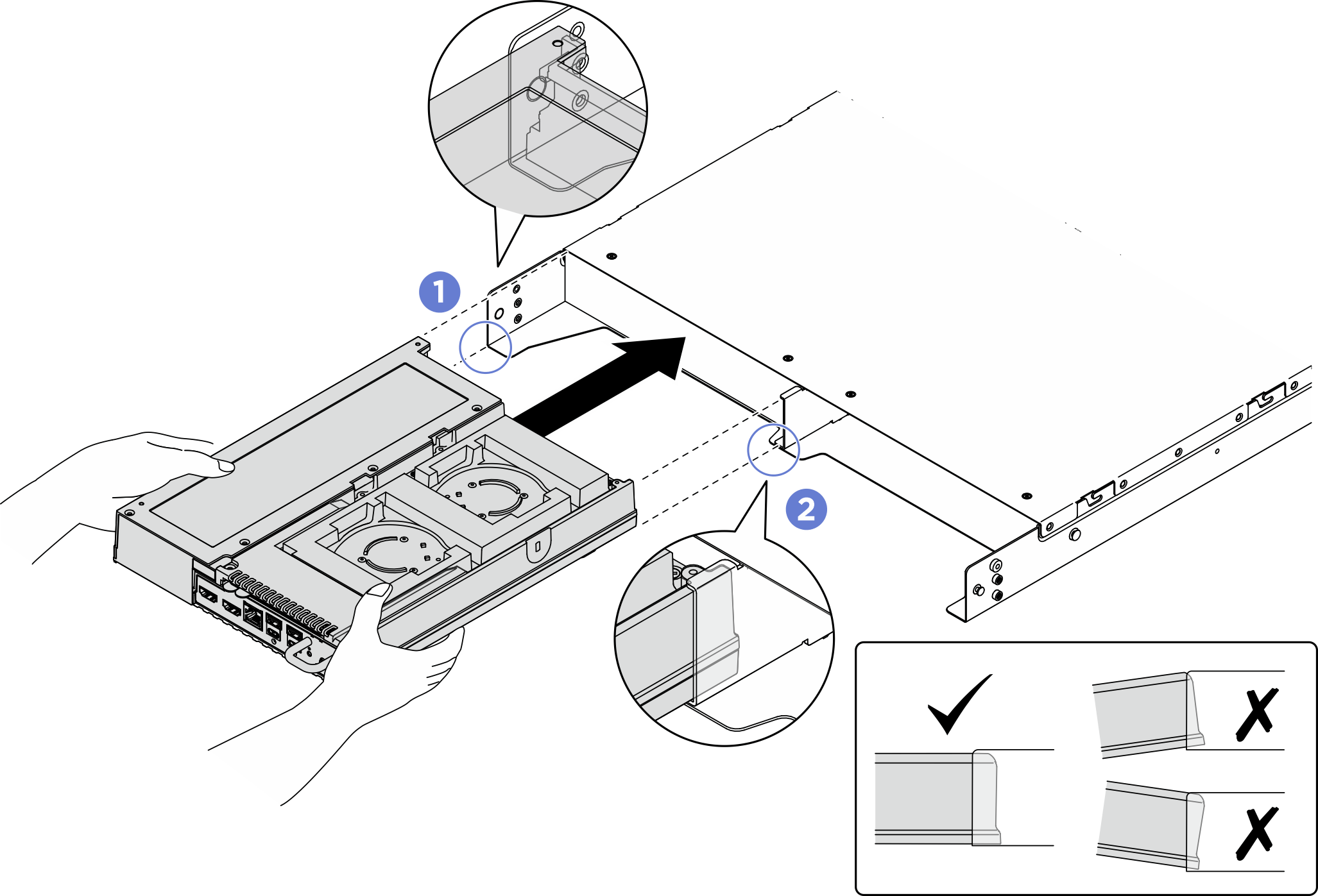
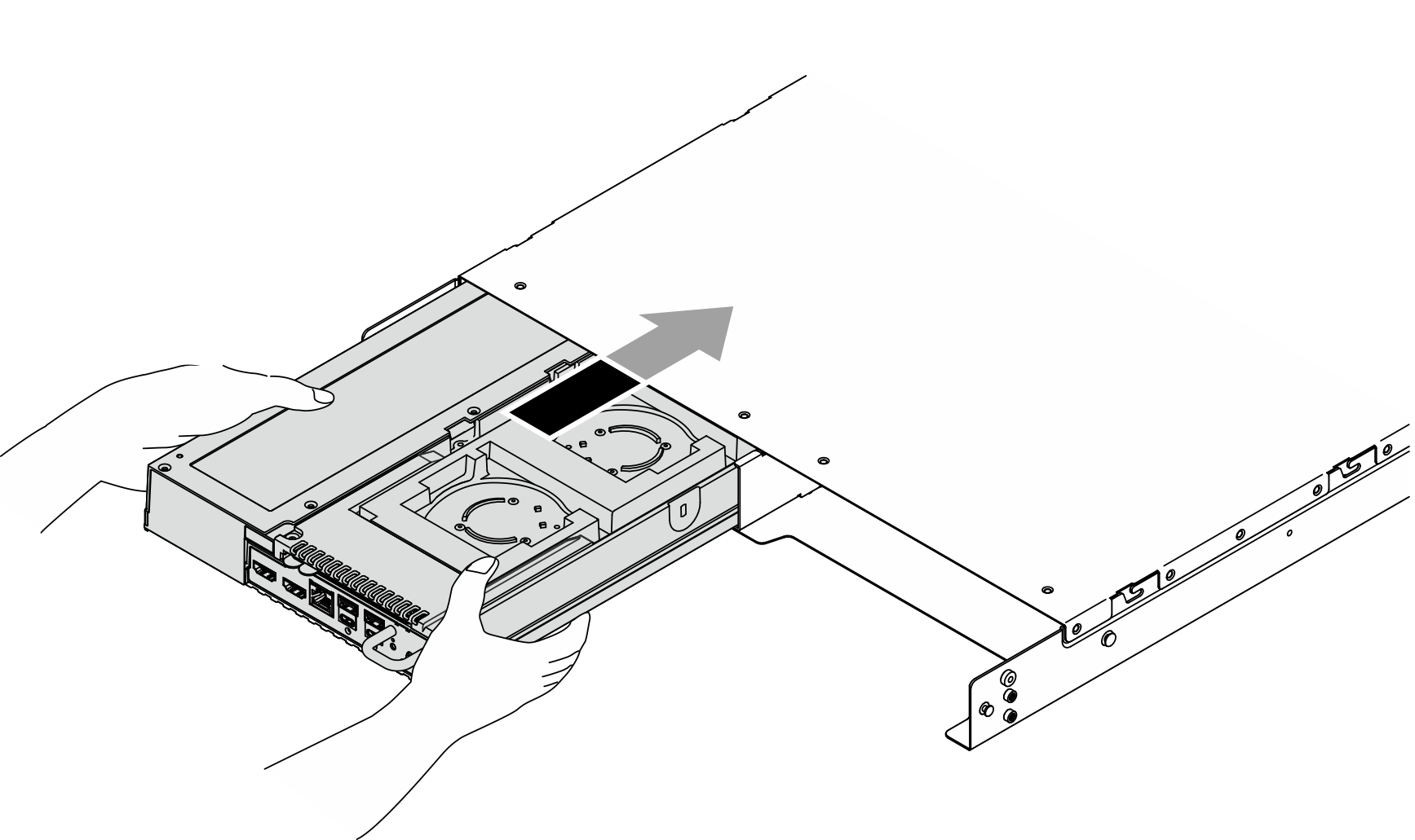
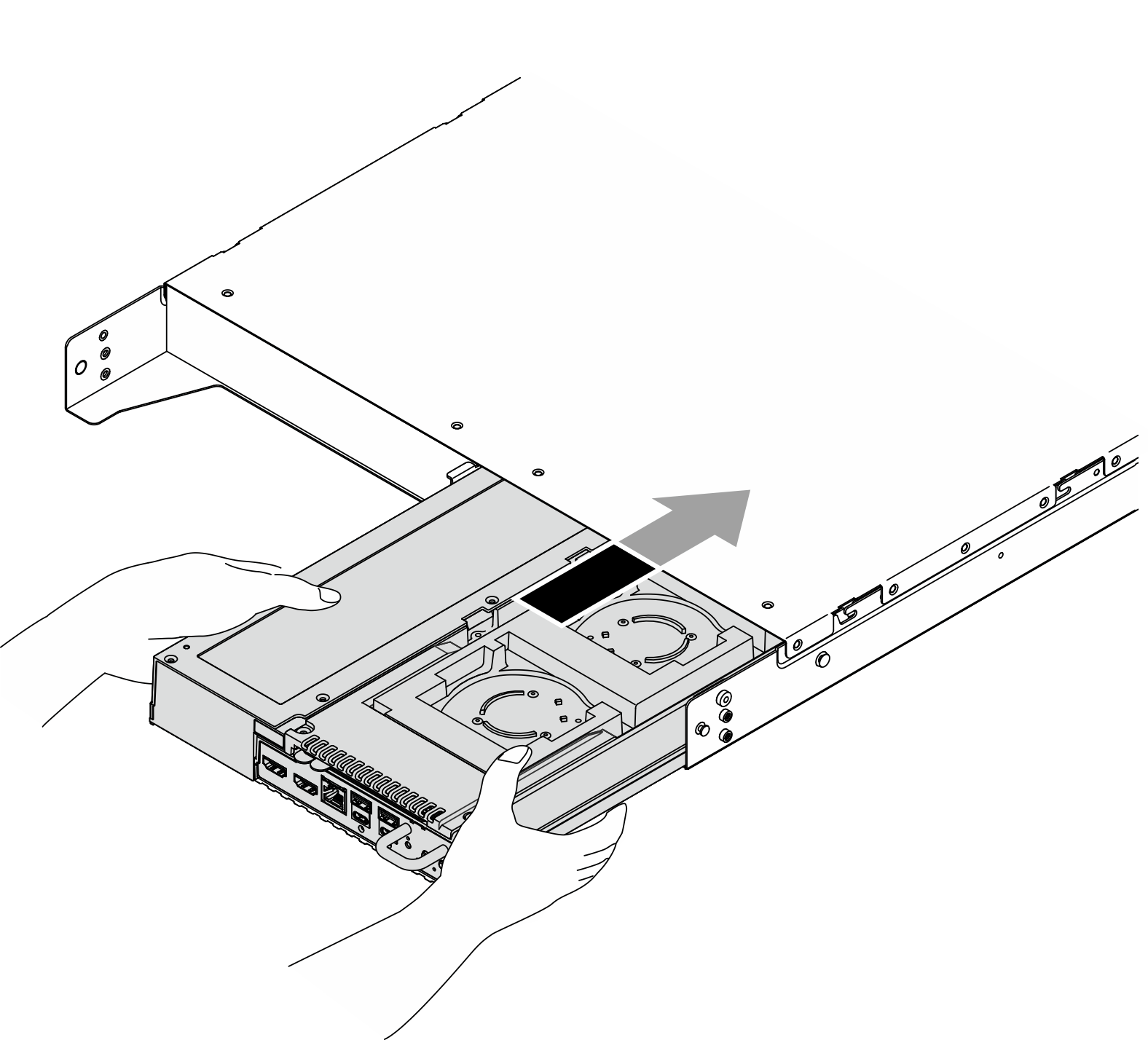
- Keep holding the node with both hands and push the node about half way into the enclosure; then, push the node forward with one hand until the node clicks into place.Figure 9. Installing the node
Install the node to 1U2N Enclosure Bay 2 / 1U3N Enclosure Bay 3
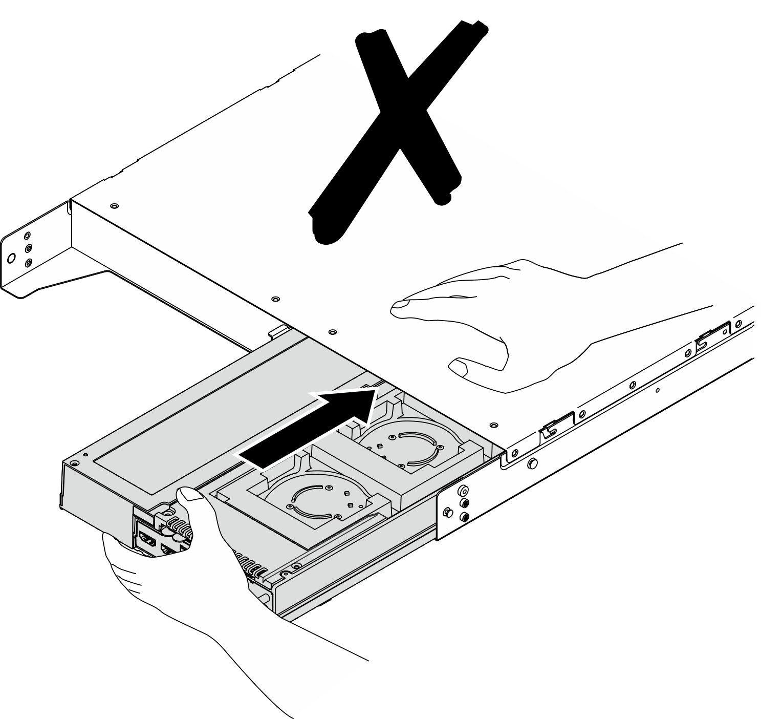
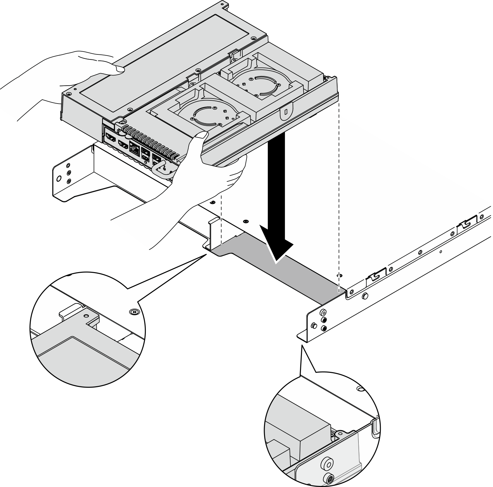
- Hold the node with both hands. Align the rear corners of node with the front of enclosure; then, lower the node down. Be careful not to let the node hit the top edge of enclosure, and make sure that the node bottom is above the enclosure bottom.Figure 10. Installing the node
- Keep holding the node with both hands and push the node about half way into the enclosure; then, push the node forward with one hand until the node clicks into place.Figure 11. Installing the node
- Hold the node with both hands. Put the rear left corner of node onto location
- (Optional) If the enclosure is with only one node installed, install a node filler into the vacant node bay.
- Insert the node filler into the node bay.
- Secure the node filler with two screws.
Figure 12. Installing the node filler - Connect all the cables to the node. To connect the power cable from power adapter, complete the following steps:
- Align the screw holes and install the power cable to the node.
- Tighten the screw and make sure the power cable is securely locked.NoteTo connect the power adapter to the node, 1U2N enclosure needs two USB-C output power cables for one power adapter, and 1U3N enclosure needs three USB-C output power cables for one power adapter. Plug in the additional power cable to the power adapter installed in an 1U3N enclosure. For more details about cable routing, see
Internal cable routing. Figure 13. Installing the power cable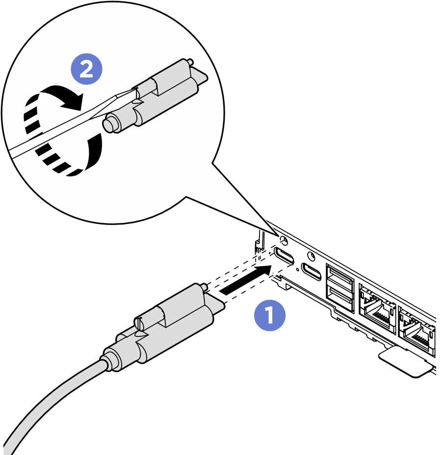
After you finish
- Install the air baffle. See Install the air baffle.
Install the middle top cover. See Install the middle top cover
- If applicable, install the crossbar to the enclosure.
- Align the crossbar with the screw holes on the enclosure; then lower the crossbar onto the enclosure. Make sure all the cables are routed properly under the crossbar.
- Tighten the two captive screws to secure the crossbar.
Figure 14. Installing the crossbar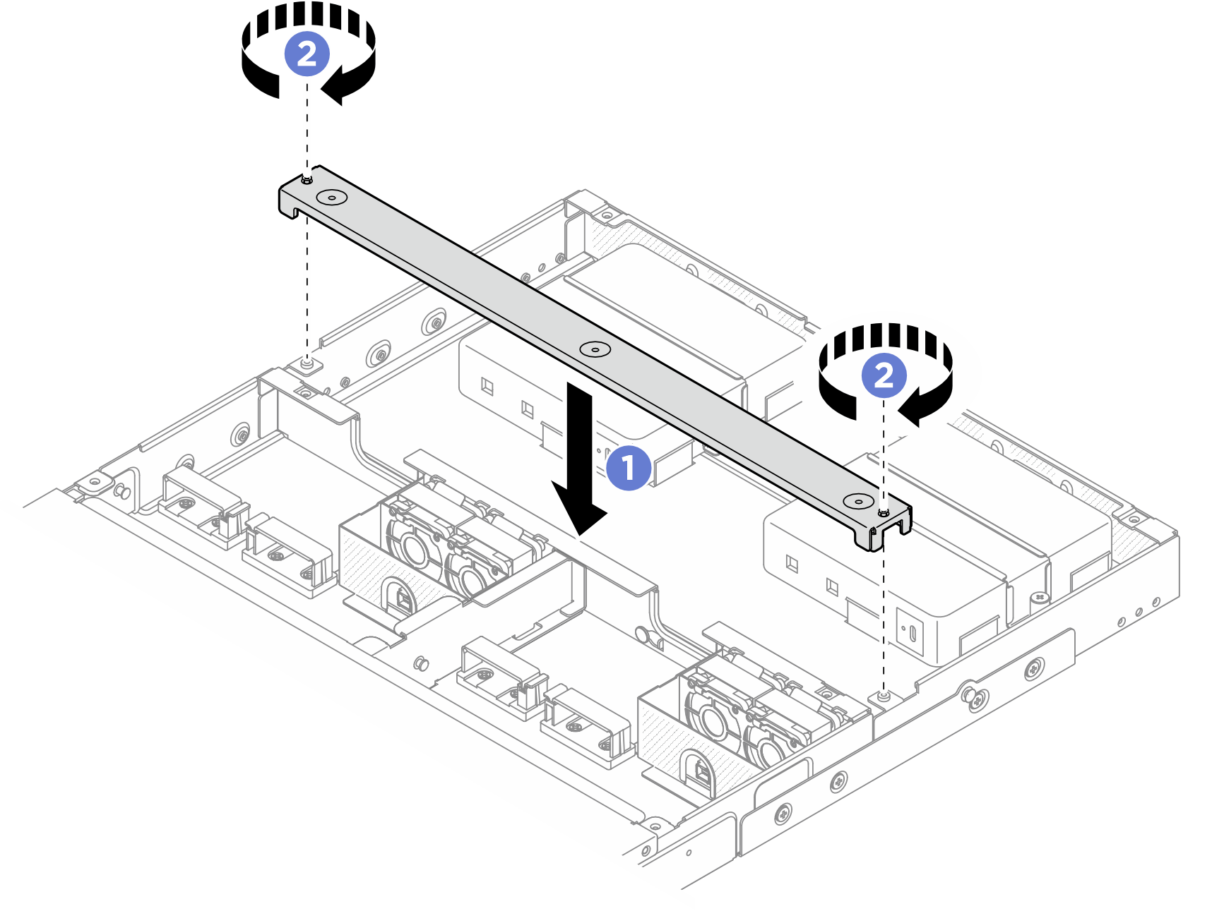
- If applicable, install the rear top cover. See Install the rear top cover.
Install the shipping bracket to the enclosure
Connect all necessary external cables to the node.
Power on the server and any peripheral devices. See Power on the server.
Procedure
- Press the captive screws on the side of the shipping bracket to ensure the captive screws are at the maximum extension as illustrated; then, push the shipping bracket toward the enclosure until it is firmly seated.Figure 15. Installing the shipping bracket
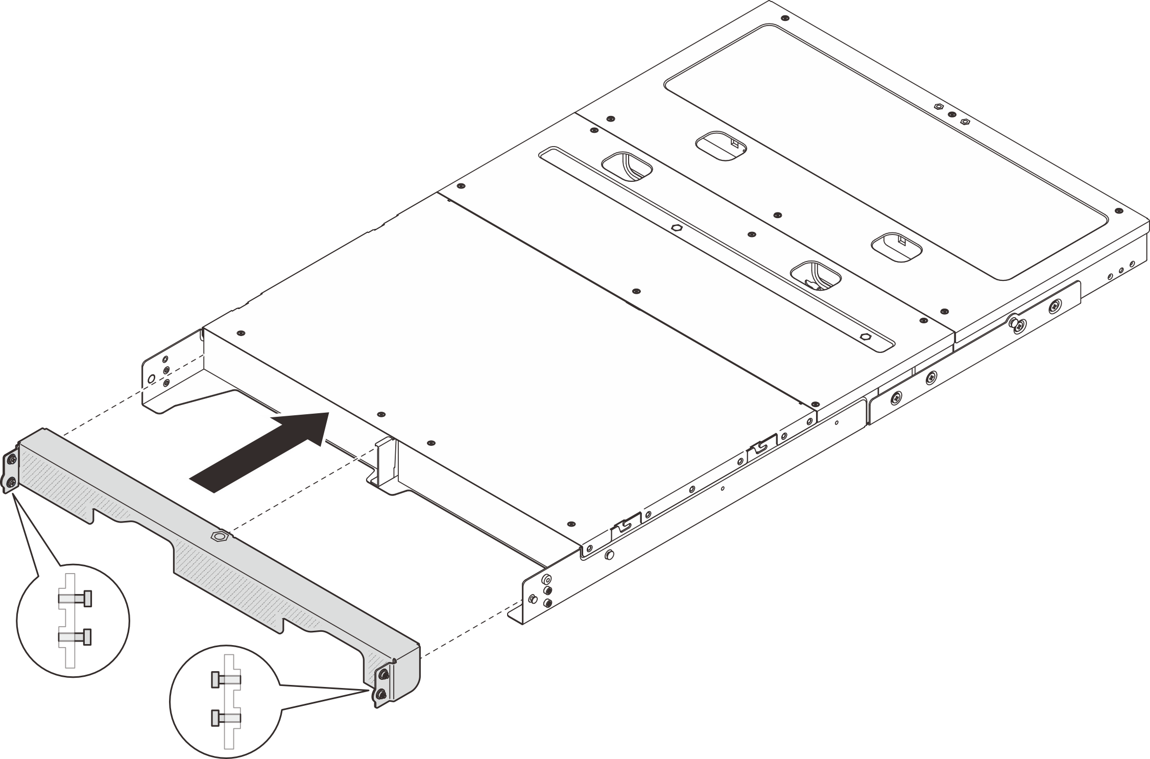
- Secure the four captive screws on both sides of the shipping bracket.Figure 16. Fastening the screws