Install a drive backplane
Follow instructions in this section to install a drive backplane to the drive cage.
About this task
To avoid potential danger, make sure to read and follow the safety information.
- S002
 CAUTIONThe power-control button on the device and the power switch on the power supply do not turn off the electrical current supplied to the device. The device also might have more than one power cord. To remove all electrical current from the device, ensure that all power cords are disconnected from the power source.
Read Installation Guidelines and Safety inspection checklist to make sure that you work safely.
Touch the static-protective package that contains the component to any unpainted metal surface on the node; then, remove it from the package and place it on a static-protective surface.
Depending on the specific configuration, there may be one or two backplanes for the drives:
- For a 7mm drive assembly, there are two backplanes. Drive backplane 1 (lower) must be installed before Drive backplane 2 (upper).
- For a 15mm drive assembly, there is only one backplane to install (Drive backplane 1 (lower)).
Depending on the specific configuration, the drives, drive bay fillers, or drive cage might look different from the illustrations in this section.
Procedure
- Make preparations for this task.
- Lay the drive cage on a flat, static-protective surface.
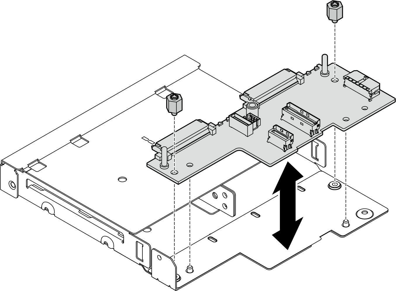
- Install Drive backplane 1 (lower) onto the drive cage.
- Tighten the two hex standoffs to secure Backplane 1 to the drive cage.Figure 1. Installation of Drive-backplane 1
 Note
NoteThe hex standoffs are designed to be used with a common Phillips screwdriver or flat-head screwdriver.
- Tighten the two hex standoffs to secure Backplane 1 to the drive cage.
- Install Drive backplane 2 (upper).
- Tighten the three screws to secure Drive-backplane 2 to Drive-backplane 1.Figure 2. Installation of Drive-backplane 2
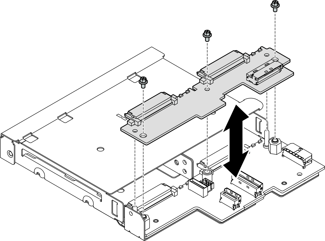
- Tighten the three screws to secure Drive-backplane 2 to Drive-backplane 1.
After this task is completed
- Proceed to install the drive cage into the node (see Install a drive cage).
- Connect all necessary cables to the drive backplane(s) (see Cable routing for the hot-swap drives).Attention
Before connecting the drive-backplane cables, make sure that the power input board module and the power module board are installed in place.
- Reinstall all the drives and drive bay fillers (if any) into the drive cage when the drive cage is in place (see Install a hot-swap drive).
- Proceed to complete the parts replacement (see Complete the parts replacement).