Install a DIMM
Use this information to install a DIMM.
Read Installation Guidelines to ensure that you work safely.
Power off the compute node (see Power off the compute node for instructions).
- If the compute node is installed in a chassis, remove it (see Remove a compute node for instructions).
- Carefully lay the compute node on a flat, static-protective surface.
Remove the compute node cover (see Remove the compute node cover for instructions).
For details about DIMM installation sequence, refer to Memory Population Reference.
If you are installing DCPMMs for the first time, follow the instructions in DC Persistent Memory Module (DCPMM) setup so that the system supports DCPMMs.
The compute node has a total of 48 dual inline memory module (DIMM) connectors. The compute node supports DDR4 DIMMs with error-correcting code (ECC) in 8 GB, 16 GB, 32 GB, and 64 GB capacity.
If you are installing an optional processor, install it before installing memory modules. See Install a processor and heat sink.
The following illustration shows the system-board components, including DIMM connectors.
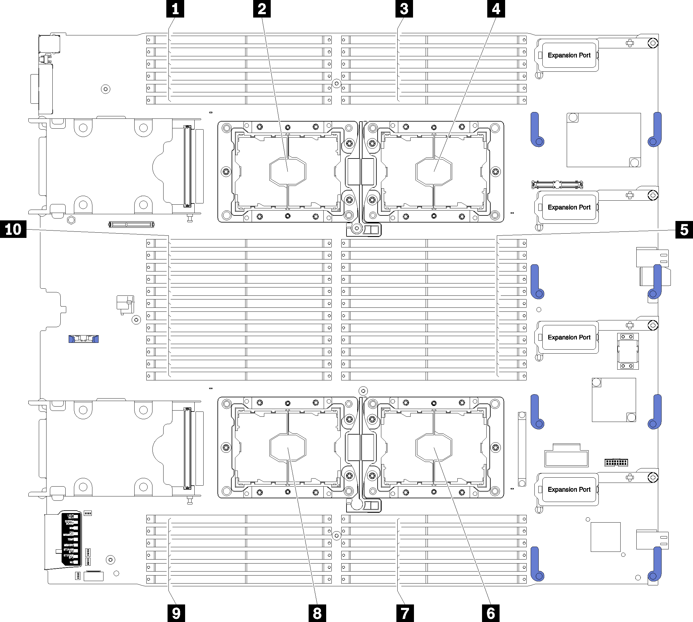
| 1 DIMM 25 – 30 | 6 Processor socket 2 |
| 2 Processor socket 3 | 7 DIMM 19 – 24 |
| 3 DIMM 1 – 6 | 8 Processor socket 4 |
| 4 Processor socket 1 | 9 DIMM 43 – 48 |
| 5 DIMM 7 – 18 | 10 DIMM 31 – 42 |
To install a DIMM, complete the following steps:
Always wear an electrostatic-discharge strap when removing or installing memory modules. Electrostatic-discharge gloves can also be used.
Never hold two or more memory modules together so that they touch. Do not stack memory modules directly on top of each other during storage.
Never touch the gold memory module connector contacts or allow these contacts to touch the outside of the memory-module connector housing.
Handle memory modules with care: never bend, twist, or drop a memory module.
Do not use any metal tools (such as jigs or clamps) to handle the memory modules, because the rigid metals may damage the memory modules.
Do not insert memory modules while holding packages or passive components, which can cause package cracks or detachment of passive components by the high insertion force.
Remove or install DIMMs for one processor at a time.
Do not mix RDIMMs and LR-DIMMs in the same compute node.
DIMMs are static-sensitive devices. The package must be grounded before it is opened.
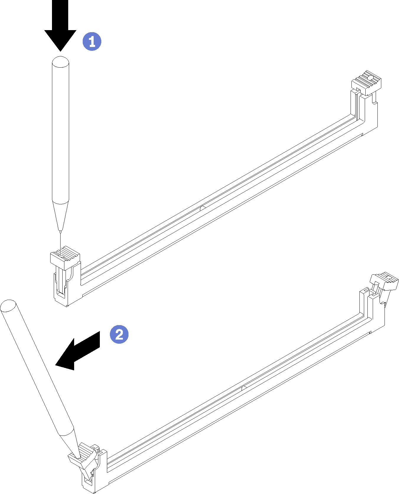
- Make sure that both retaining clips on the DIMM connector are in the open position.Figure 2. Opening DIMM latch
 Note
NoteIf necessary due to space constraints, you can use a pointed tool to open the retaining clips. Place the tip of the tool in the recess on the top of the retaining clip; then, carefully rotate the retaining clip away from the DIMM connector.
Make sure you use firm and solid pointed tool to open the retaining clips. Do not use pencil. In case there are any fragments of the tool fall into the compute node, caused unnecessary damage.
The retaining clips for adjacent DIMM connectors of processor and processor cannot be opened at the same time. Remove or install the DIMMs for each processor one at a time.
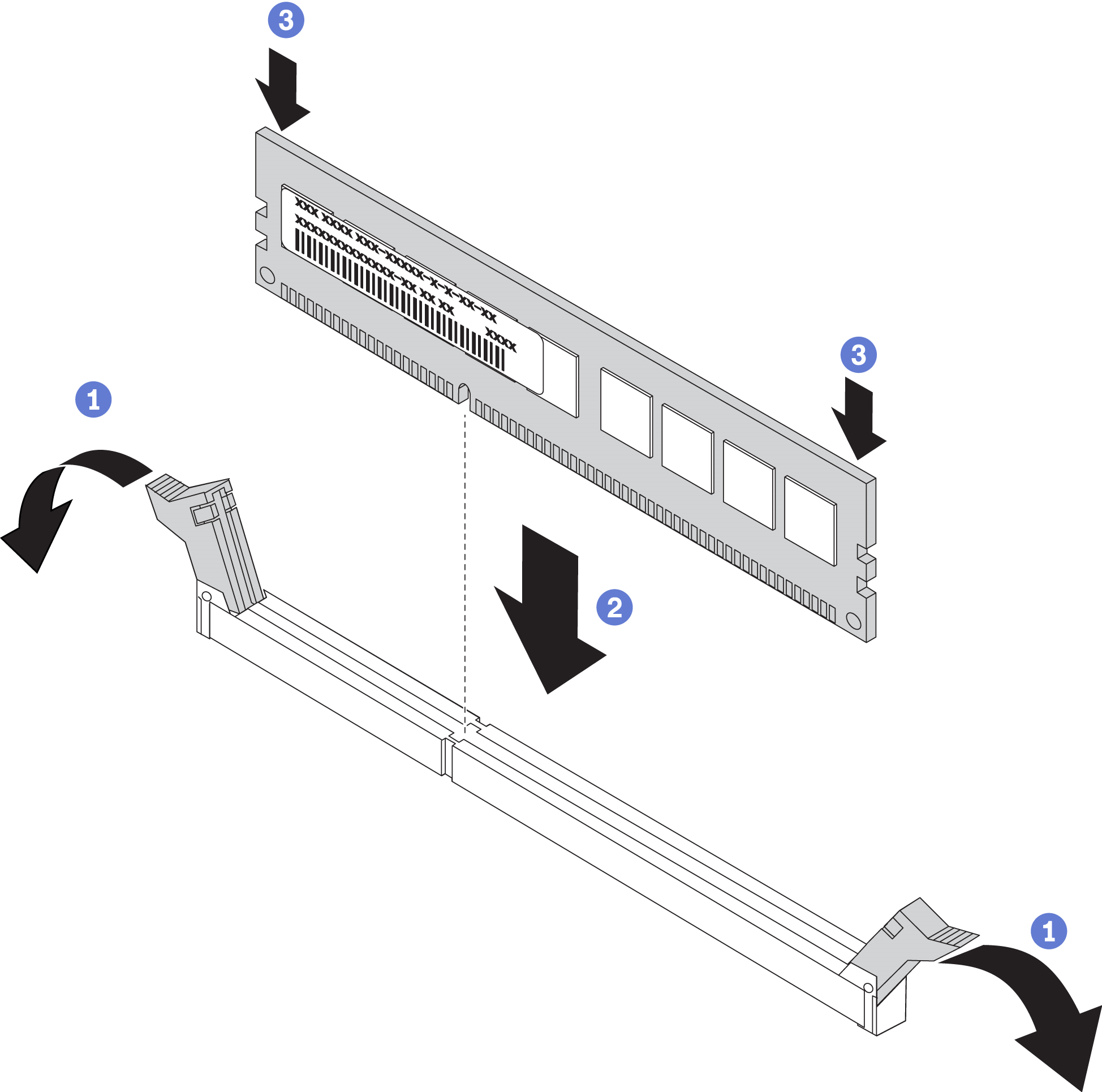
AttentionTo avoid breaking the retaining clips or damaging the DIMM connector, handle the clips gently. - Firmly press both ends of the DIMM straight down into the DIMM connector until the retaining clips snap into the locked position.Figure 3. DIMM installation
Install the air baffle (see Install the air baffle for instructions).
AttentionTo maintain proper system cooling, do not operate the compute node without an air baffle installed over the DIMM connectors.- Install the compute node cover onto the compute node (see Install the compute node cover for instructions).
- Install the compute node into the chassis (see Install a compute node for instructions).
If you have installed a DCPMM:
Update the system firmware to the latest version (see Update the firmware).
Make sure the firmware of all the DCPMM units is the latest version. If not, update it to the latest version (see Updating firmware on managed devices with LXCA).
Restore the data that have been backed up if necessary.
Demo video