Processor-board connectors for cable routing
The following illustrations show the internal connectors on the processor board that are used for internal cable routing.
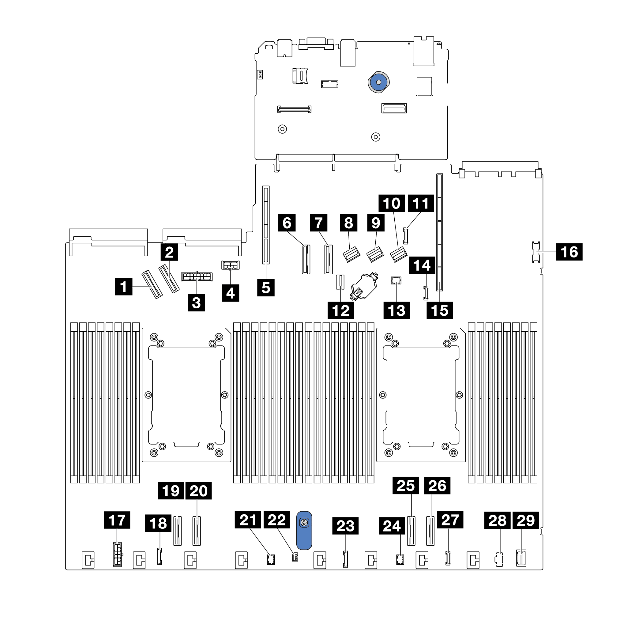
Figure 1. Processor-board connectors for cable routing
| Connectors | |
|---|---|
| 1 PCIe connector 5 | 16 Front USB connector |
| 2 PCIe connector 6 | 17 Internal RAID power connector |
| 3 Front backplane power connector | 18 CFF Re-timer clock connector |
| 4 GPU and rear backplane power connector | 19 PCIe connector 4 |
| 5 Riser 2 Slot | 20 PCIe connector 3 |
| 6 PCIe connector 7 | 21 Pump 2 connector |
| 7 PCIe connector 8 | 22 Intrusion switch connector |
| 8 SAS/SATA connector 0 | 23 Front panel connector |
| 9 SAS/SATA connector 1 | 24 Front panel LCD connector |
| 10 SAS/SATA connector 2 | 25 PCIe connector 2 |
| 11 Rear backplane sideband connector | 26 PCIe connector 1 |
| 12 M.2/7mm backplane signal connector | 27 External diagnostics connector |
| 13 Pump 1 connector | 28 M.2 power connector |
| 14 Leak detection connector | 29 Front VGA connector |
| 15 Riser 1 slot | |
Give documentation feedback