Front I/O module
Use the section to understand the cable routing for front I/O modules.
Cable routing for front I/O modules
For the locations of front I/O module connectors on the processor board, see Processor-board connectors for cable routing for details.
The illustrations show the cabling scenario for server models with 2.5-inch and 3.5-inch front drive bays. Location of each connector on the front of the server varies by models. For detailed locations of front I/O components for different models, see Front view and Front I/O module.
Figure 1. Cable routing for a front I/O module on 2.5'' chassis 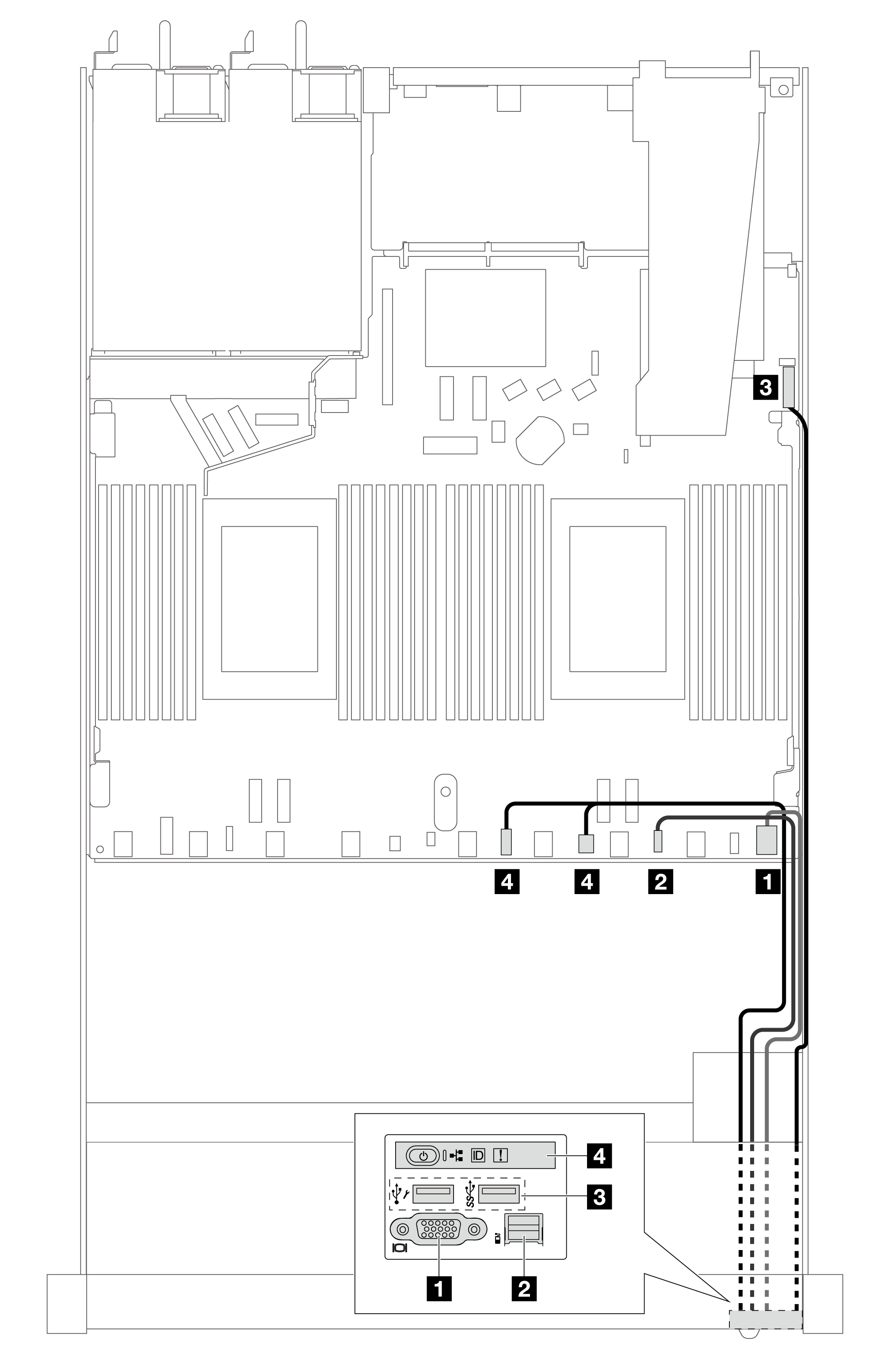 | Figure 2. Cable routing for the front I/O module on 3.5'' chassis 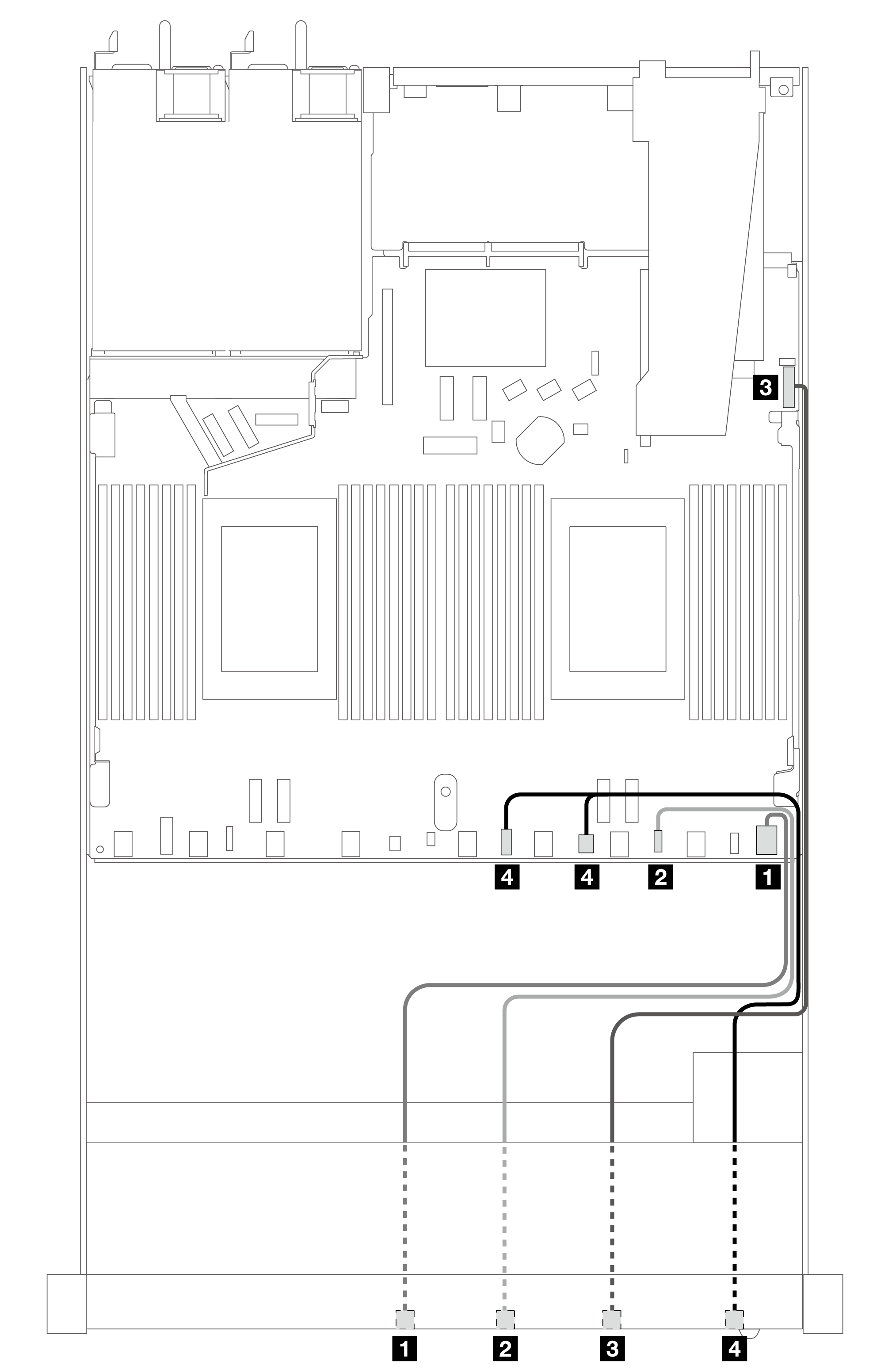 |
| From | To |
|---|---|
| 1 VGA connector | 1 VGA connector |
| 2 External diagnostics handset connector Note | 2 External diagnostics handset connector |
| 3 Front USB connector | 3 Front USB connector |
| 4 Front operator panel | 4 Left: front panel connector 4 Right: front panel LCD connector |
Note
The external diagnostics connector is not available on certain front I/O modules of 10 x 2.5-inch server models.
Give documentation feedback