M.2 drive backplane
This section provides cable routing information for the M.2 drives. Your server supports M.2 SATA/NVMe drive backplanes.
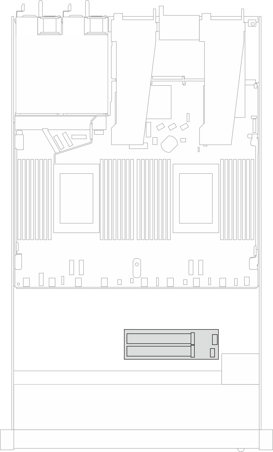
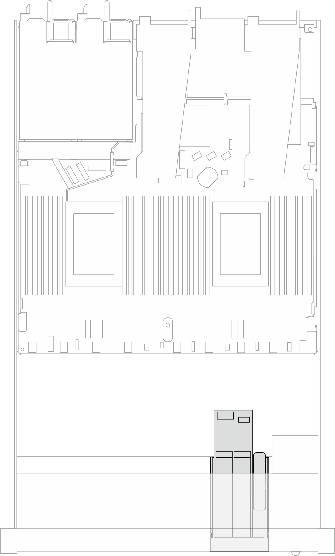
Locations of M.2 drive assemblies
The locations of M.2 drive assemblies vary in different configuration. The server has two locations for M.2 drive assemblies.
Figure 1. An M.2 drive assembly in the 2.5/3.5-inch drive chassis  | Figure 2. An M.2 drive assembly in the 16-EDSFF drive chassis  |
Cable routing of the M.2 drive backplane
For the locations of M.2 connectors on the backplanes and the processor board, see M.2 backplane and M.2 drive replacement and Processor-board connectors for cable routing for details.
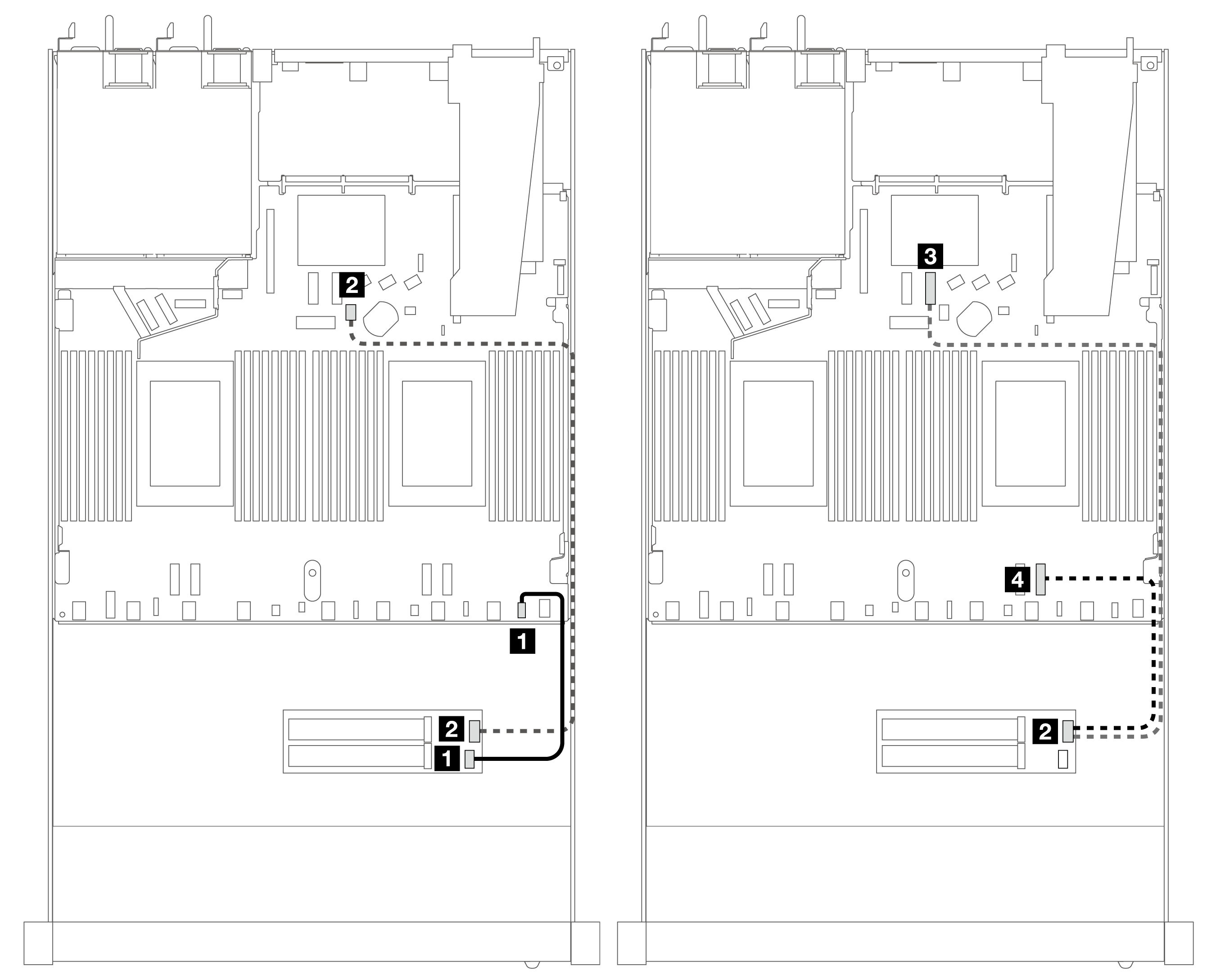
The following illustration and table list the M.2 drive backplane supported:
Cable routing for M.2 SATA/NVMe x4 backplane

| From | To |
|---|---|
| 1 M.2 power | 1 M.2 power connector |
| 2 M.2 signal | 2 7mm/M.2 signal port on the processor board (for SATA signal) |
| 3 PCIe 8 (for NVMe signal, connected when two processors are installed) | |
| 4 PCIe 1 (for NVMe signal, connected when one processor is installed) |
Note
The illustrations above take the M.2 drive assembly in the 2.5/3.5-inch drive chassis for an example. In the 16-EDSFF drive chassis, the cable routing method remains the same.
Give documentation feedback