Rear NVMe drive backplane
Use this section to understand the cable routing of rear NVMe backplanes with both one and two processors installed.
The onboard connection of rear NVMe drive backplane are different based on whether one or two processors installed.
For the locations of rear NVMe drive backplane connectors on the processor board, see Processor-board connectors for cable routing for details.
Figure 1. Rear NVMe backplane cable routing with two processors installed 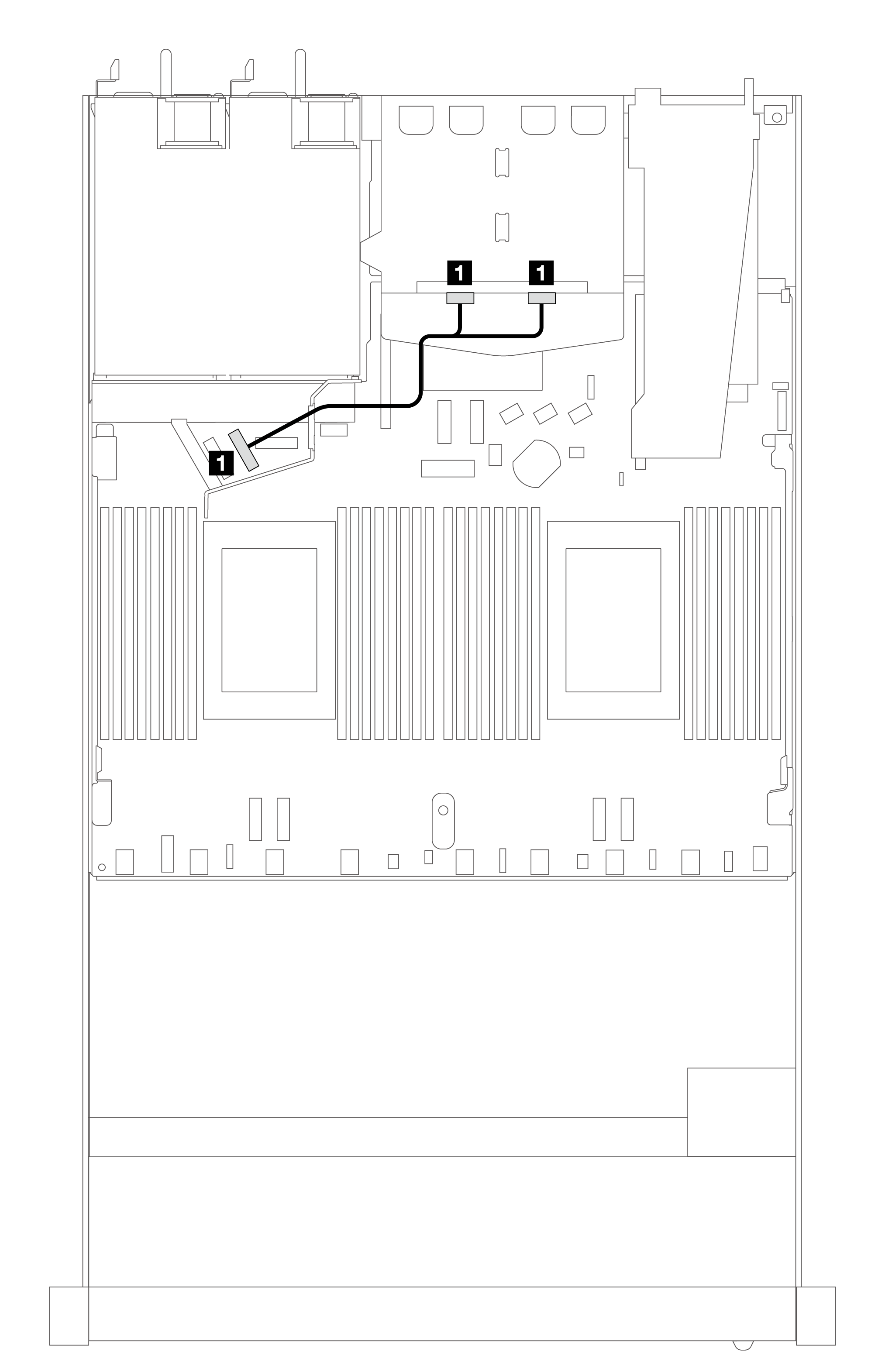 | Figure 2. Rear NVMe backplane cable routing with one processor installed 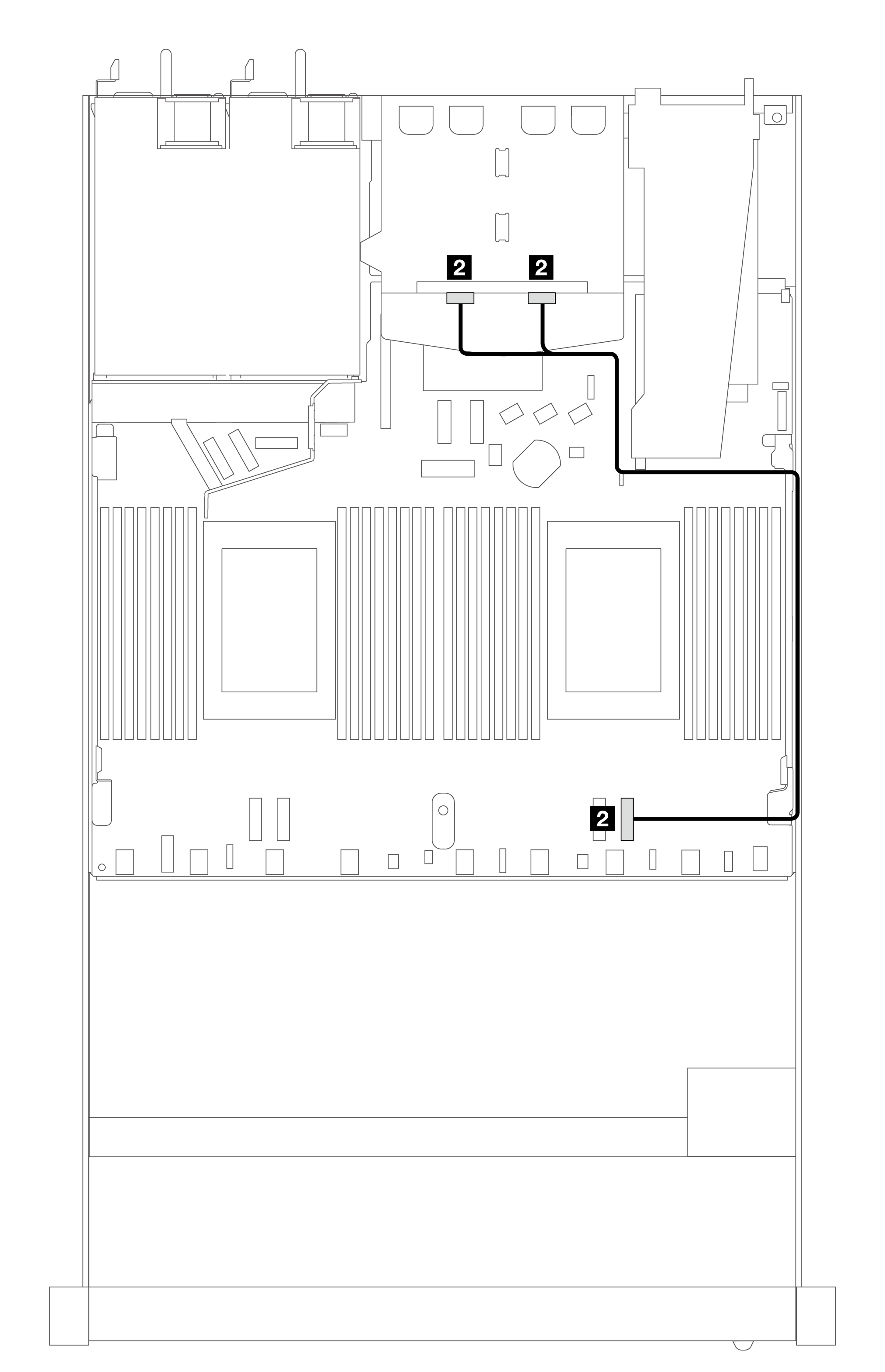 |
| 1 From NVMe 0, 1 to PCIe 6 | 2 From NVMe 0, 1 to PCIe 1 |
Rear NVMe backplane cable routing with 10 x 2.5'' AnyBay backplane (Gen 5) installed
Note
With the 10 x 2.5'' AnyBay backplane (Gen 5) installed, the rear NVMe connection to the processor board is different from other customary configuration.
Figure 3. Mapping between the rear NVMe backplane signal cable and the processor board
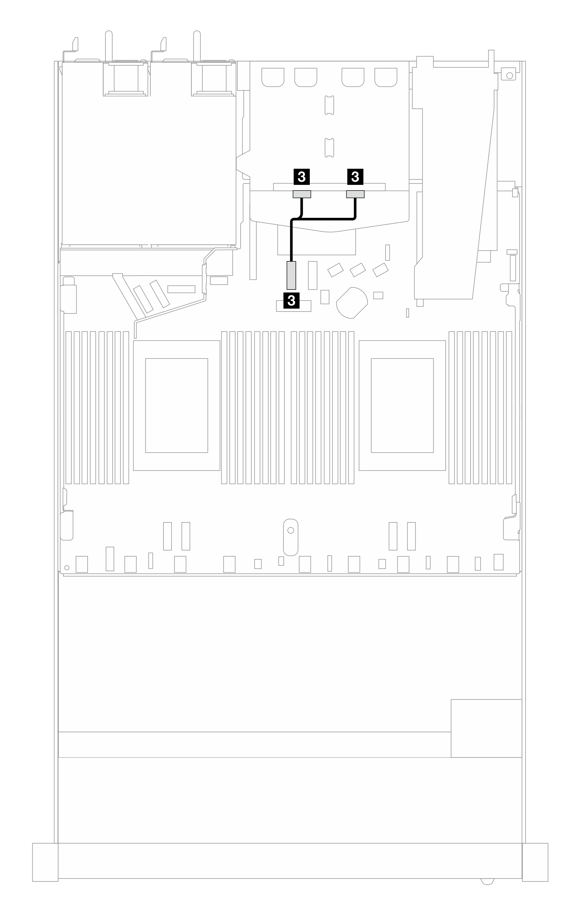
3 From NVMe 0, 1 to PCIe 7
Give documentation feedback