Processor and heat sink replacement (trained technicians only)
Use this information to remove and install a processor or a heat sink.
This task must be operated by trained technicians that are certified by Lenovo Service. Do not attempt to remove or install the part without proper training and qualification.
Before replacing a processor, check the current PSB fuse policy. See Service process before replacement at Service process for updating PSB fuse state (Lenovo service technicians only).
After replacing a processor, ensure that the processor fuse status is expected without unexpected XCC event logs. See Service process after replacing a processor at Service process for updating PSB fuse state (Lenovo service technicians only). The fuse status must be the same as the original fuse status of the server.
You can also fuse or unfuse processors through UEFI setup. See UEFI Setting Guide for details.
When the server has a L2AM (The Lenovo Neptune Liquid to Air Module) installed, you must apply for a L2AM module handle (LACM heat sink bracket) first if you need to install or remove the system board assembly or processor. However, while replacing the old L2AM with a new one, you do not need to apply for a module handle (LACM heat sink bracket) as the new L2AM package contains it.
Before reusing a processor or heat sink, make sure you use Lenovo proven alcohol cleaning pad and thermal grease.
Each processor socket must always contain a cover or a processor. When replacing a processor, protect the empty processor socket with a cover.
Do not touch the processor socket or processor contacts. Processor-socket contacts are very fragile and easily damaged. Contaminants on the processor contacts, such as oil from your skin, can cause connection failures.
Do not allow the thermal grease on the processor or heat sink to come in contact with anything. Contact with any surface can compromise the thermal grease, rendering it ineffective. Thermal grease can damage components, such as the electrical connectors in the processor socket.
This section is for processor and heat sink replacement. For the replacement of the L2AM (The Lenovo Neptune Liquid to Air Module), refer to The Lenovo Neptune® Liquid to Air Module replacement (trained technicians only).
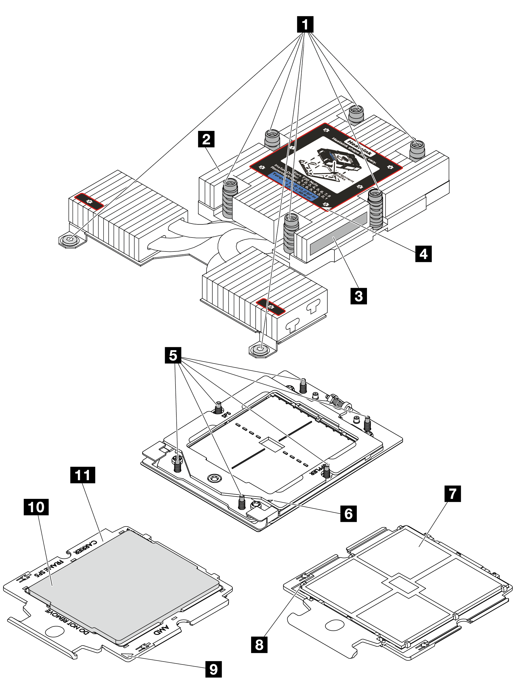
| 1 Captive screws (8) | 2 Heat sink |
| 3 Processor identification label | 4 Heat sink triangular mark |
| 5 Screw bolts (6) | 6 Retention frame triangular mark |
| 7 Processor contacts | 8 Processor triangular mark |
| 9 Carrier triangular mark | 10 Processor carrier |
| 11 Processor heat spreader |