System board assembly replacement (trained technicians only)
Follow instructions in this section to remove and install the system I/O board and processor board, which assembled as a system board assembly.
This task must be operated by trained technicians that are certified by Lenovo Service. Do not attempt to remove or install the part without proper training and qualification.
When the server has a L2AM (The Lenovo Neptune Liquid to Air Module) installed, you must apply for a L2AM module handle (LACM heat sink bracket) first if you need to install or remove the system board assembly or processor. However, while replacing the old L2AM with a new one, you do not need to apply for a module handle (LACM heat sink bracket) as the new L2AM package contains it.
- If you need to replace a processor board and a firmware and RoT security module together, do the following:
Check the current PSB fuse policy before replacement. See Service process before replacement at Service process for updating PSB fuse state (Lenovo service technicians only).
Ensure that the processor fuse status is expected without unexpected XCC event logs after replacement. See Service process after replacing a processor board and a firmware and RoT security module together at Service process for updating PSB fuse state (Lenovo service technicians only). The fuse status must be the same as the original fuse status of the server.
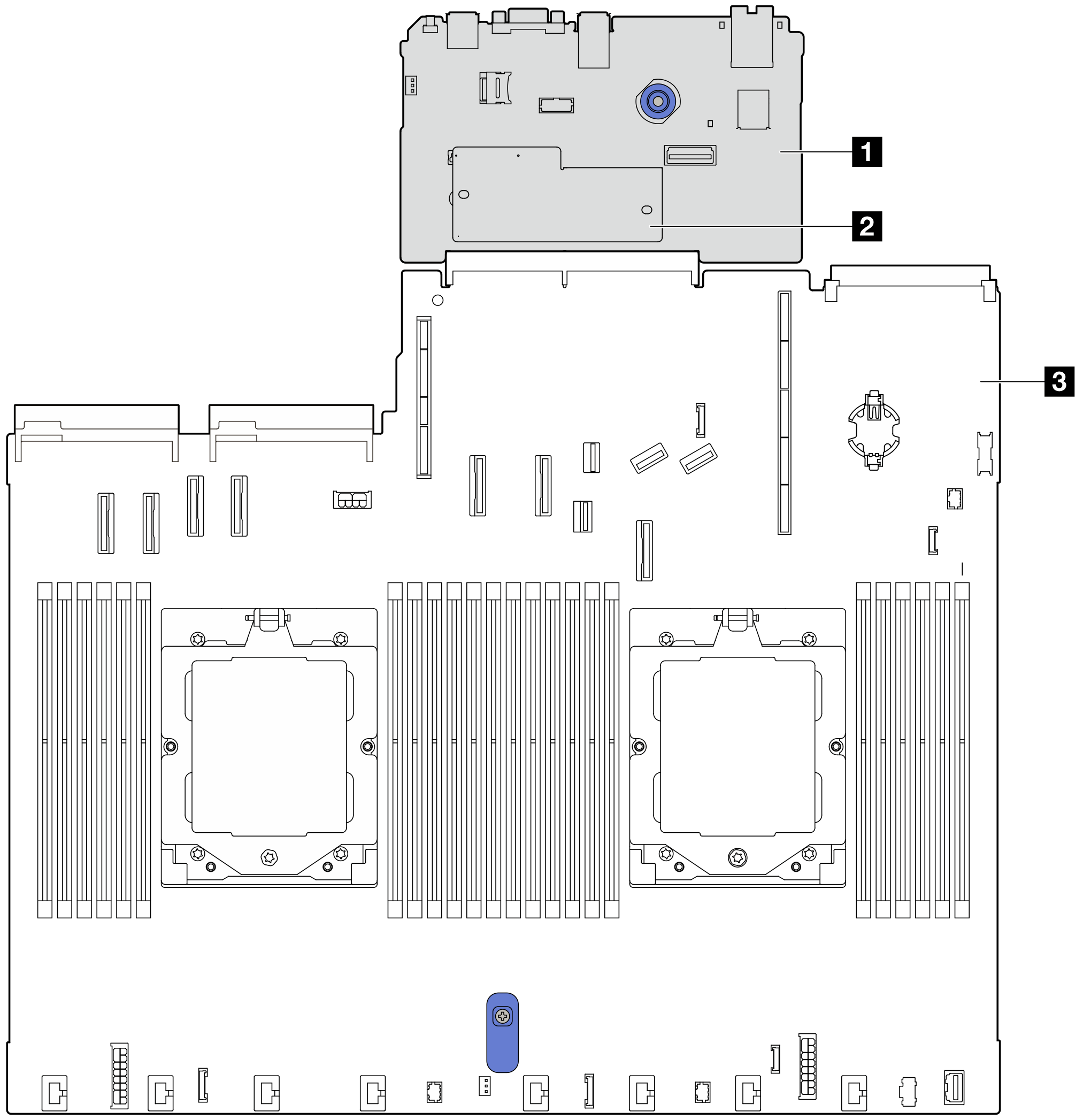
| 1 System I/O board | 3 Processor board |
| 2 Firmware and RoT security module |