Front 24 x 2.5" NVMe + Middle 8 x 2.5" NVMe + Rear 4 x 2.5" NVMe
This topic provides cable routing information for the front 24 x 2.5" NVMe + middle 8 x 2.5" NVMe + rear 4 x 2.5" NVMe configuration.
Note
This configuration is supported only when two processors are installed.
NVMe cable routing to BP1
Figure 1. NVMe cable routing to BP1
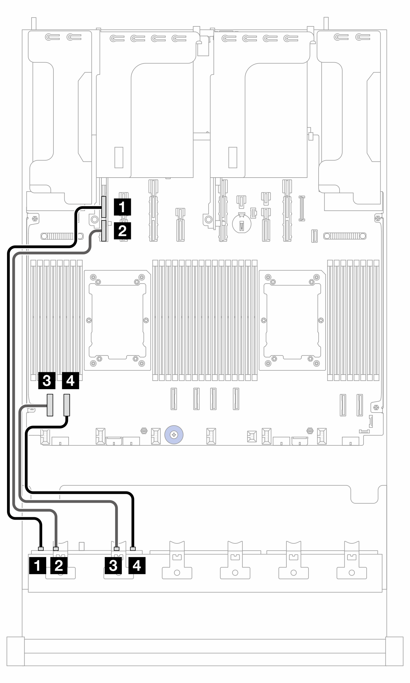
| From (BP1) | To (processor board) | Cable length |
|---|---|---|
| 1 NVMe 0-1 | 1 PCIe 15A | 600 mm |
| 2 NVMe 2-3 | 2 PCIe 15B | 600 mm |
| 3 NVMe 4-5 | 3 PCIe 8 | 350 mm |
| 4 NVMe 6-7 | 4 PCIe 7 | 350 mm |
NVMe cable routing to BP2
Figure 2. Cable routing to BP2
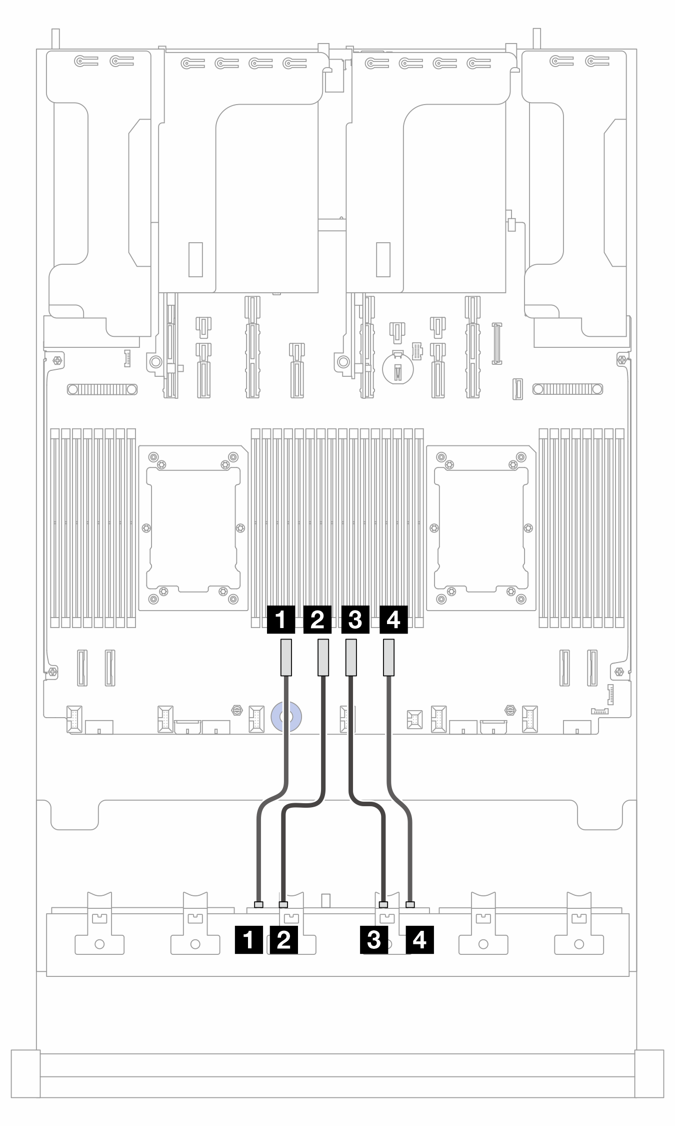
| From (BP2) | To (processor board) | Cable length |
|---|---|---|
| 1 NVMe 0-1 | 1 PCIe 6 | 250 mm |
| 2 NVMe 2-3 | 2 PCIe 5 | 250 mm |
| 3 NVMe 4-5 | 3 PCIe 4 | 250 mm |
| 4 NVMe 6-7 | 4 PCIe 3 | 250 mm |
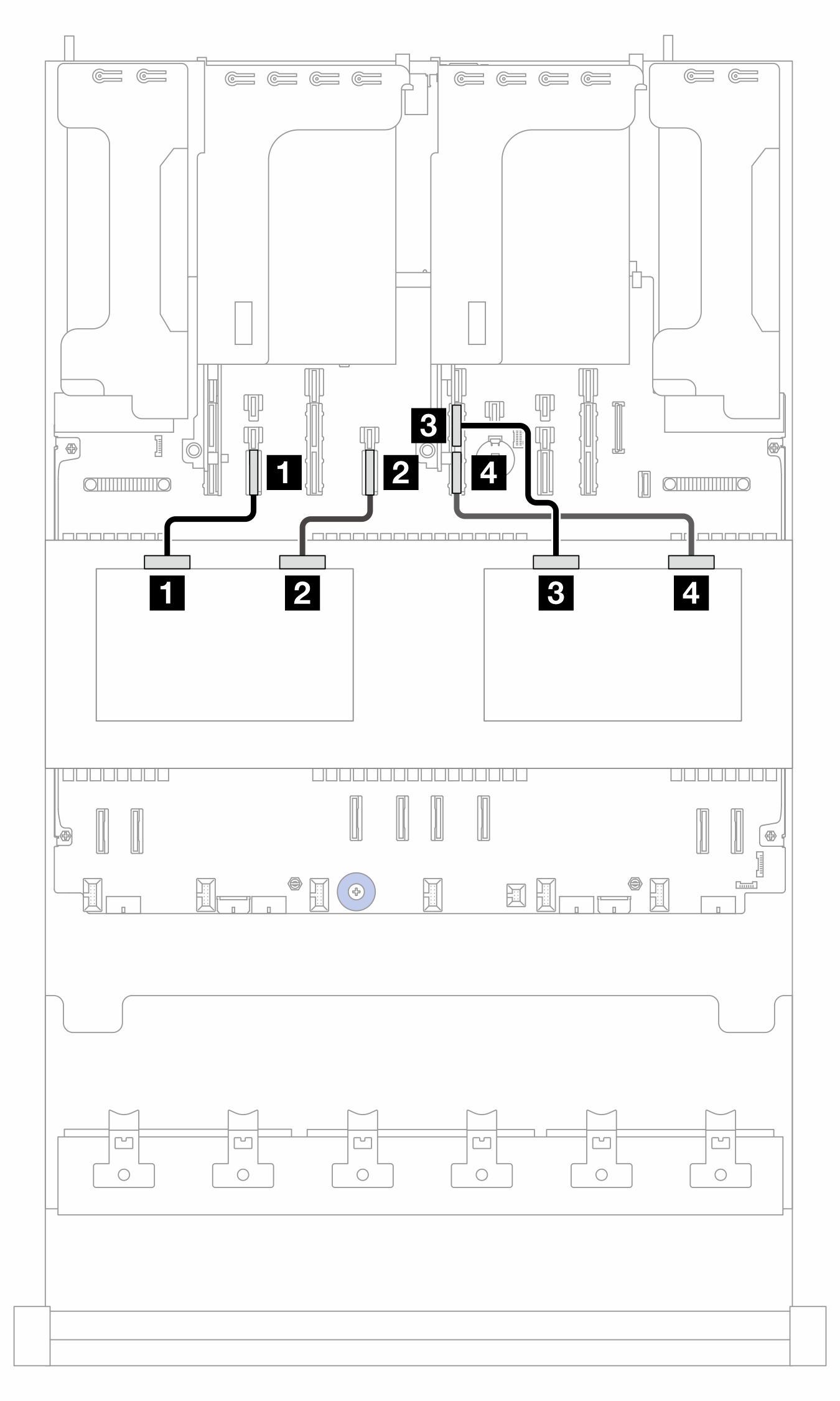
NVMe cable routing to BP3
Figure 3. NVMe cable routing to BP3
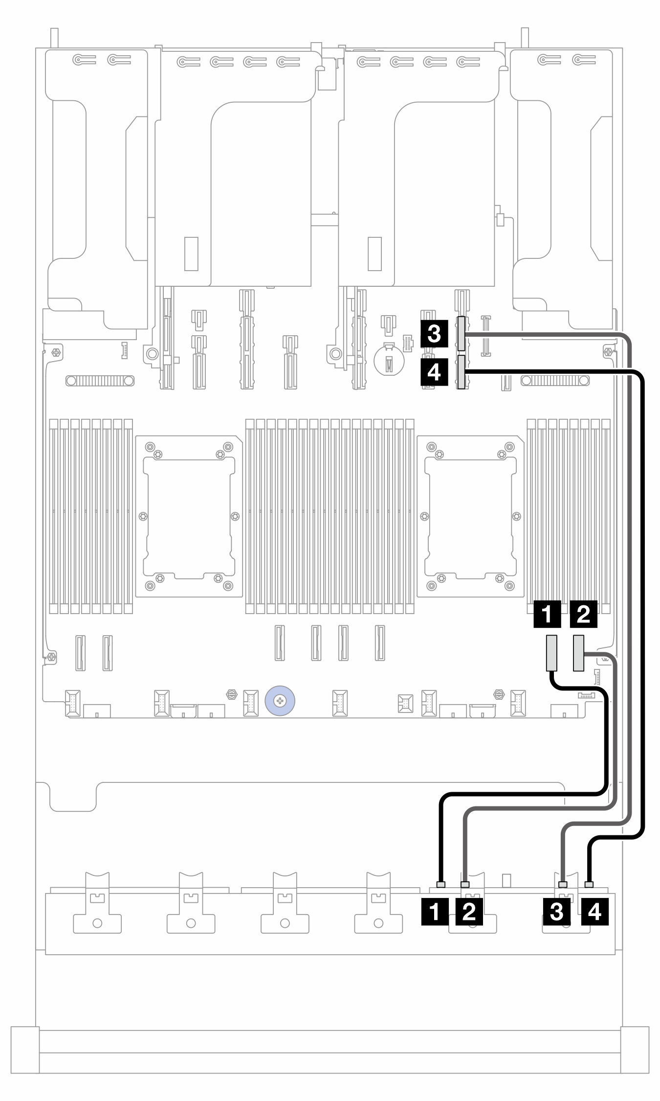
| From (BP3) | To (processor board) | Cable length |
|---|---|---|
| 1 NVMe 0-1 | 1 PCIe 2 | 350 mm |
| 2 NVMe 2-3 | 2 PCIe 1 | 350 mm |
| 3 NVMe 4-5 | 3 PCIe 9A | 600 mm |
| 4 NVMe 6-7 | 4 PCIe 9B | 600 mm |
NVMe cable routing to BP9
Figure 4. NVMe cable routing to BP9
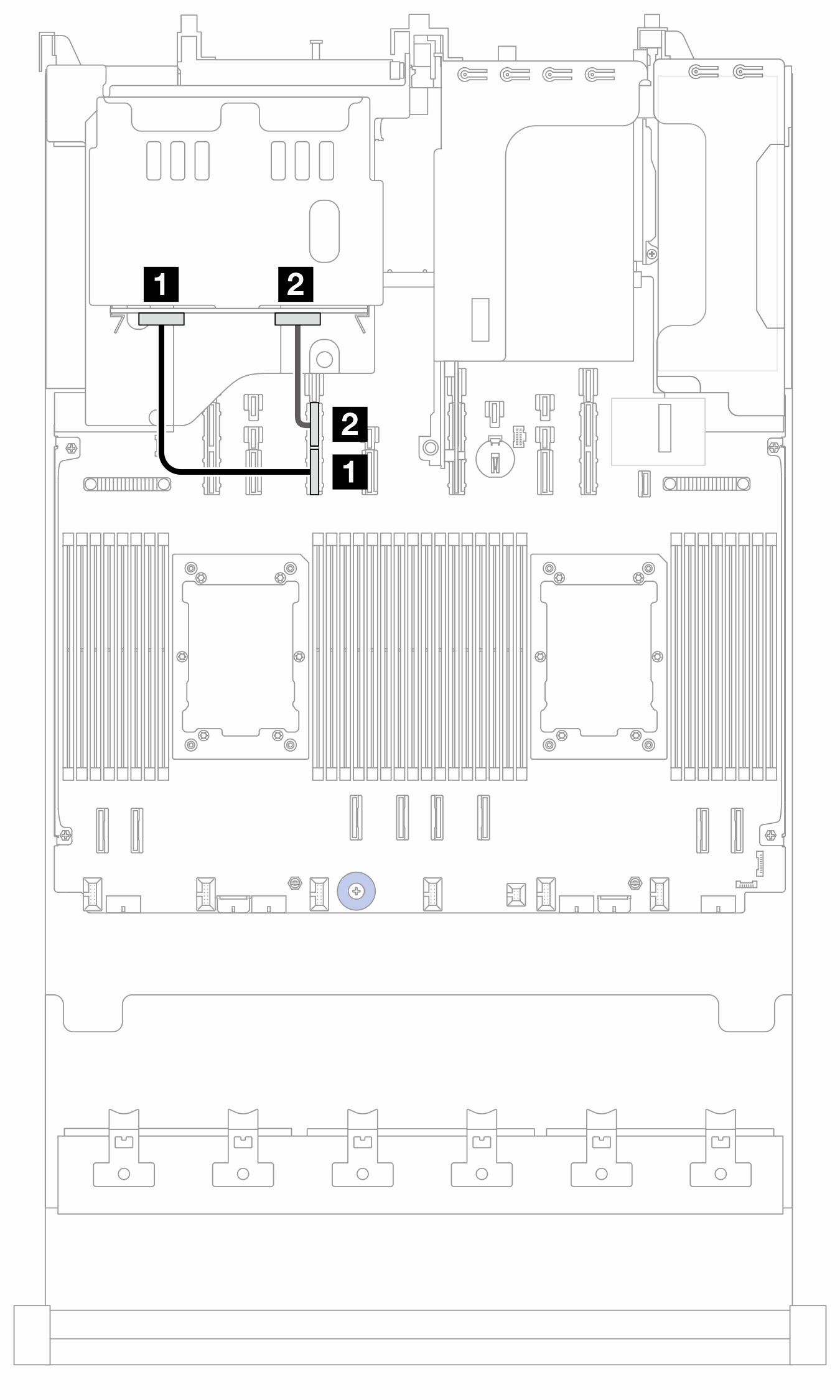
| From (BP9) | To (processor board) | Cable length |
|---|---|---|
| 1 NVMe 2-3 | 1 PCIe 13B | 280 mm |
| 2 NVMe 0-1 | 2 PCIe 13A | 280 mm |
NVMe cable routing to BP10 and BP11
Figure 5. NVMe cable routing to BP10 and BP11
| From | To (processor board) | Cable length |
|---|---|---|
| 1 BP10: NVMe 0-1 | 1 PCIe 14 | 280 mm |
| 2 BP10: NVMe 2-3 | 2 PCIe 12 | 280 mm |
| 3 BP11: NVMe 0-1 | 3 PCIe 11A | 280 mm |
| 4 BP11: NVMe 2-3 | 4 PCIe 11B | 280 mm |
Give documentation feedback