Drive backplane cable routing: 2.5-inch chassis with Compute Complex Neptune Core Module
This section provides backplane cable connection information for server models with 2.5" front drive bays and Compute Complex Neptune Core Module.
Power cable connections
For power cable connections, see Drive backplane cable routing: 2.5-inch chassis without Compute Complex Neptune Core Module.
Signal cable connections
The configuration numbers in the table below are for descriptive purposes only.
| BP config. | Storage controller | Config. No. |
|---|---|---|
| 8 x 2.5" SAS/SATA (BP1) 8 x 2.5" AnyBay (tri-mode) | 1 x SFF 8i/16i | 1 |
| 1 x CFF 16i | 2 | |
| 8 x 2.5" NVMe (BP1) | N/A | 3 |
| 8 x 2.5" AnyBay (BP1) | 1 x SFF 8i/16i | 4 |
| 1 x CFF 16i | 5 | |
| 16 x 2.5" SAS/SATA (BP1 + BP2) 16 x 2.5" AnyBay (tri-mode) | 2 x SFF 8i or 1 x SFF 16i | 6 |
| 1 x CFF 16i | 7 | |
| 16 x 2.5" NVMe (BP1 + BP2) | N/A | 8 |
| 8 x 2.5" AnyBay + 8 x 2.5" NVMe (BP1 + BP2) | 1 x SFF 8i/16i | 9 |
| 1 x CFF 16i | 10 | |
| 8 x 2.5" SAS/SATA + 8 x 2.5" AnyBay (BP1 + BP2) | 2 x SFF 8i or 1 x SFF 16i | 11 |
| 1 x CFF 16i | 12 | |
| 8 x 2.5" SAS/SATA + 8 x 2.5" NVMe (BP1 + BP2) | 1 x SFF 8i/16i | 13 |
| 1 x CFF 16i | 14 |
Cable routing to SFF 8i/16i adapter (config. 1/4/6/9/11/13)
Note
The location of the adapter and cable connectors on the adapter may differ from those shown in the illustration. For details, see the table below.
Cable 2 is needed only in configurations with 8 x 2.5" SAS/SATA or AnyBay BP2.
Figure 1. Cable routing to SFF 8i/16i adapter
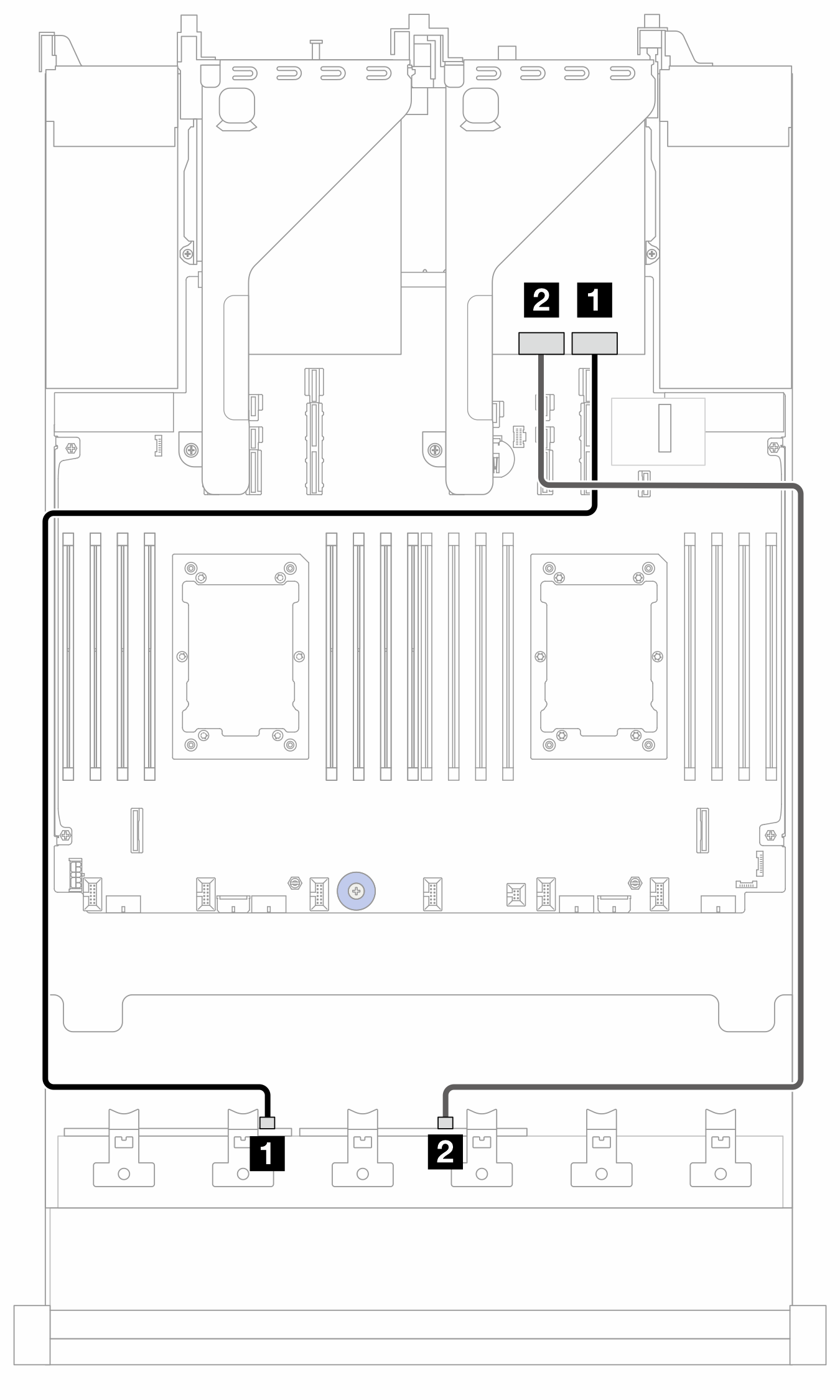
| From | To | Cable length | |
|---|---|---|---|
| 1 BP1: SAS | 1 8i adapter:
| 1 16i adapter:
| 900 mm |
| 2 BP2: SAS | 2 8i adapter:
| 2
| 900 mm |
NVMe cable routing (config. 8/9/10/11/12/13/14)
Note
NVMe cable routing to BP1 is applicable only to configurations with 8 x 2.5" AnyBay or NVMe BP1 (config. 8/9/10).
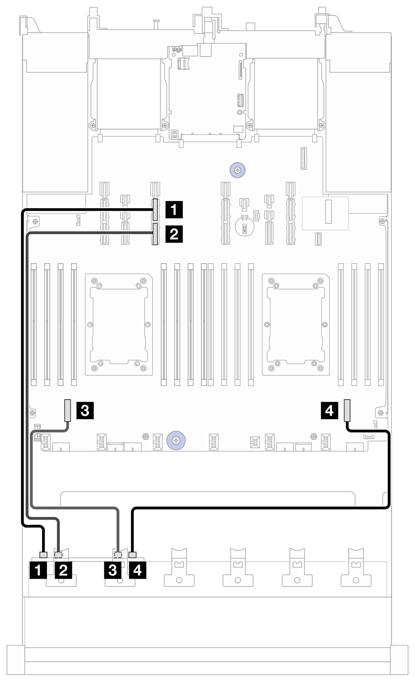
Figure 2. NVMe cable routing to BP1
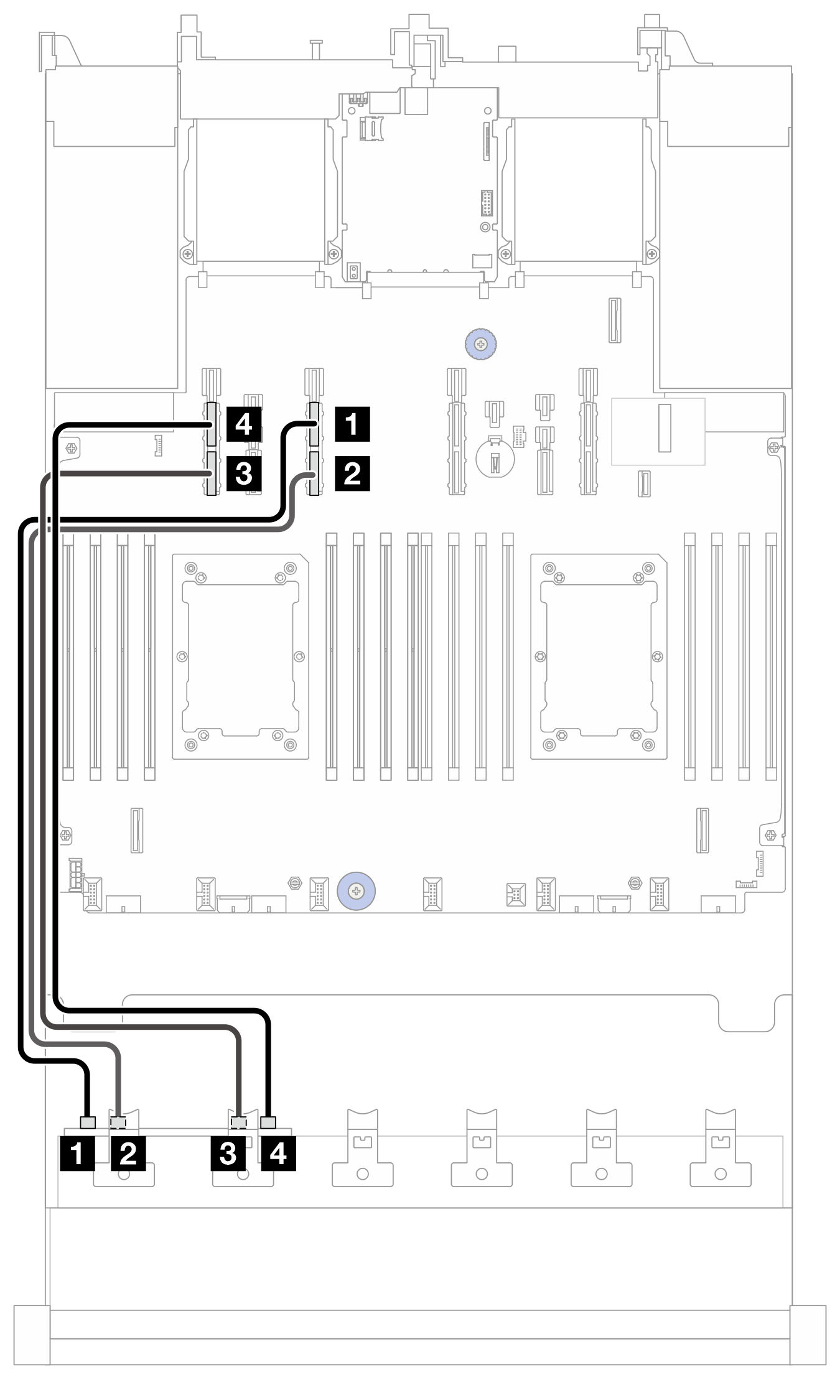
| From (BP1) | To (processor board) | Cable length |
|---|---|---|
| 1 NVMe 0-1 | 1 PCIe 13A | 600 mm |
| 2 NVMe 2-3 | 2 PCIe 13B | 600 mm |
| 3 NVMe 4-5 | 3 PCIe 15B | 600 mm |
| 4 NVMe 6-7 | 4 PCIe 15A | 600 mm |
Figure 3. NVMe cable routing to BP2
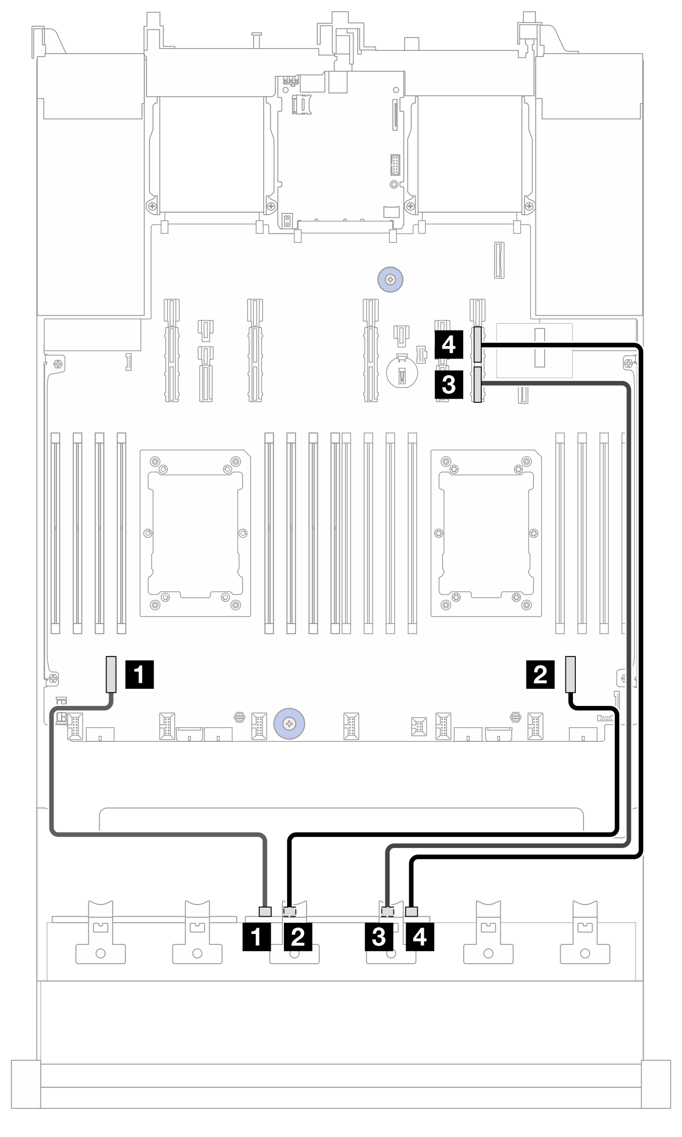
| From (BP2) | To (processor board) | Cable length |
|---|---|---|
| 1 NVMe 0-1 | 1 PCIe 7 | 350 mm |
| 2 NVMe 2-3 | 2 PCIe 2 | 450 mm |
| 3 NVMe 4-5 | 3 PCIe 9B | 700 mm |
| 4 NVMe 6-7 | 4 PCIe 9A | 700 mm |
Cable routing to CFF 16i adapter (config. 5/10/12/14)
Note
Cable 3 is needed only in config. 12.
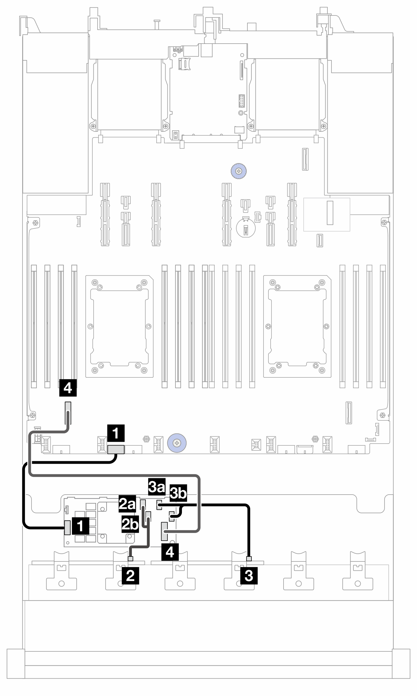
Figure 4. Cable routing to CFF 16i adapter (config. 5/10/12/14)
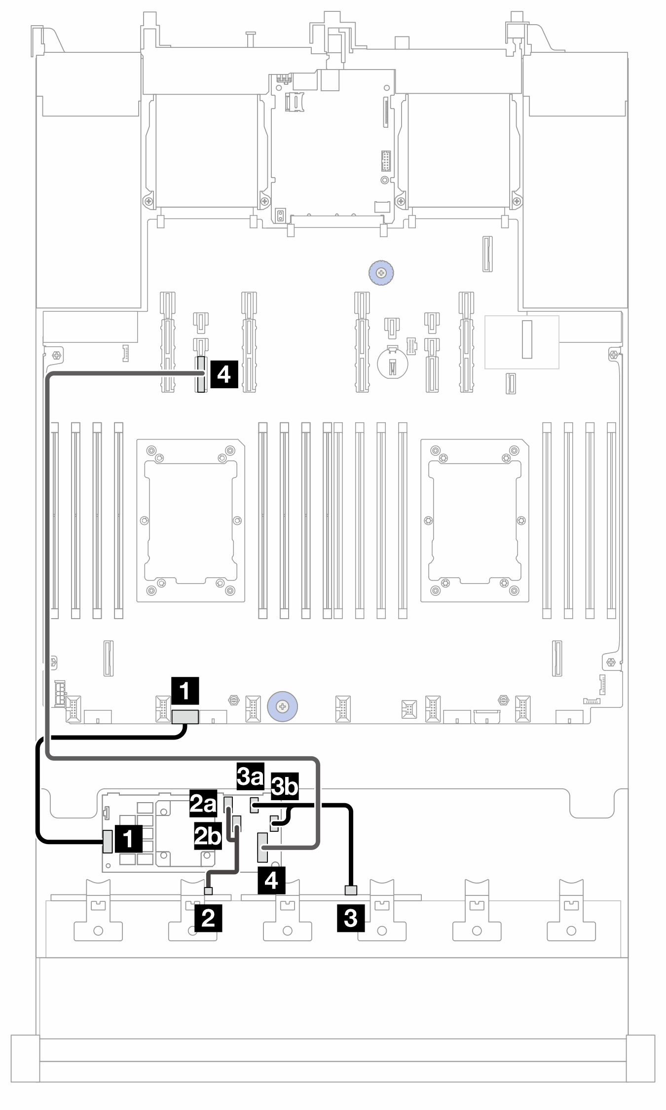
2P: two processors; 1P: one processor; PB: processor board
| From (CFF 16i adapter) | To | Cable length |
|---|---|---|
| 1 POWER | 1 PB: RAID PWR | 210 mm |
| 2a C0 | 2 BP1: SAS | 140/140 mm |
| 2b C1 | ||
| 3a C2 | 3 BP2: SAS | 140/140 mm |
| 3b C3 | ||
| 4 MB (CFF INPUT) | 4 PB: PCIe 14 | 900 mm |
NVMe cable routing (config. 3/4/5)
Figure 5. NVMe cable routing to BP1
| From (BP1) | To (processor board) | Cable length |
|---|---|---|
| 1 NVMe 0-1 | 1 PCIe 13A | 600 mm |
| 2 NVMe 2-3 | 2 PCIe 13B | 600 mm |
| 3 NVMe 4-5 | 3 PCIe 7 | 350 mm |
| 4 NVMe 6-7 | 4 PCIe 2 | 450 mm |
Cable routing to CFF 16i adapter (config. 2/7)
Note
Cable 3 is needed only in config. 7.
Figure 6. Cable routing to CFF 16i adapter (config. 2/7)
2P: two processors; 1P: one processor; PB: processor board
| From (CFF 16i adapter) | To | Cable length |
|---|---|---|
| 1 POWER | 1 PB: RAID PWR | 210 mm |
| 2a C0 | 2 BP1: SAS | 140/140 mm |
| 2b C1 | ||
| 3a C2 | 3 BP2: SAS | 140/140 mm |
| 3b C3 | ||
| 4 MB (CFF INPUT) | 4 PB: PCIe 7 | 450 mm |
Give documentation feedback