Kabelführung der Rückwandplatine für Laufwerke: 2,5-Zoll-Gehäuse mit Compute Complex Neptune Core Module
Dieser Abschnitt enthält Informationen zu den Kabelanschlüssen an der Rückwandplatine für Servermodelle mit 2,5-Zoll-Laufwerkpositionen an der Vorderseite Compute Complex Neptune Core Module.
Netzkabelverbindungen
Informationen zu Kabelanschlüssen finden Sie unter Kabelführung der Rückwandplatine für Laufwerke: 2,5-Zoll-Gehäuse ohne Compute Complex Neptune Core Module.
Signalkabelverbindungen
Die Konfigurationsnummern in der folgenden Tabelle dienen lediglich beschreibenden Zwecken.
| BP-Konfig. | Speichercontroller | Konfig. Nr. |
|---|---|---|
| 8 x 2,5-Zoll-SAS/SATA (BP1) 8 x 2,5-Zoll-AnyBay (Tri-Modus) | 1 x SFF 8i/16i | 1 |
| 1 x CFF 16i | 2 | |
| 8 x 2,5-Zoll-NVMe (BP1) | – | 3 |
| 8 x 2,5-Zoll-AnyBay (BP1) | 1 x SFF 8i/16i | 4 |
| 1 x CFF 16i | 5 | |
| 16 x 2,5-Zoll-SAS/SATA (BP1 + BP2) 16 x 2,5-Zoll-AnyBay (Tri-Modus) | 2 x SFF 8i oder 1 x SFF 16i | 6 |
| 1 x CFF 16i | 7 | |
| 16 x 2,5-Zoll-NVMe (BP1 + BP2) | – | 8 |
| 8 x 2,5-Zoll-AnyBay + 8 x 2,5-Zoll-NVMe (BP1 + BP2) | 1 x SFF 8i/16i | 9 |
| 1 x CFF 16i | 10 | |
| 8 x 2,5-Zoll-SAS/SATA + 8 x 2,5-Zoll-AnyBay (BP1 + BP2) | 2 x SFF 8i oder 1 x SFF 16i | 11 |
| 1 x CFF 16i | 12 | |
| 8 x 2,5-Zoll-SAS/SATA + 8 x 2,5-Zoll-NVMe (BP1 + BP2) | 1 x SFF 8i/16i | 13 |
| 1 x CFF 16i | 14 |
Kabelführung zum SFF 8i/16i Adapter (Konfig. 1/4/6/9/11/13)
Anmerkung
Die Position der Adapter- und Kabelanschlüsse am Adapter kann von der Abbildung abweichen. Weitere Informationen finden Sie in der folgenden Tabelle.
Kabel 2 wird nur in Konfigurationen mit 8 x 2,5-Zoll-SAS/SATA oder AnyBay BP2 benötigt.
Abbildung 1. Kabelführung zum SFF 8i/16i Adapter
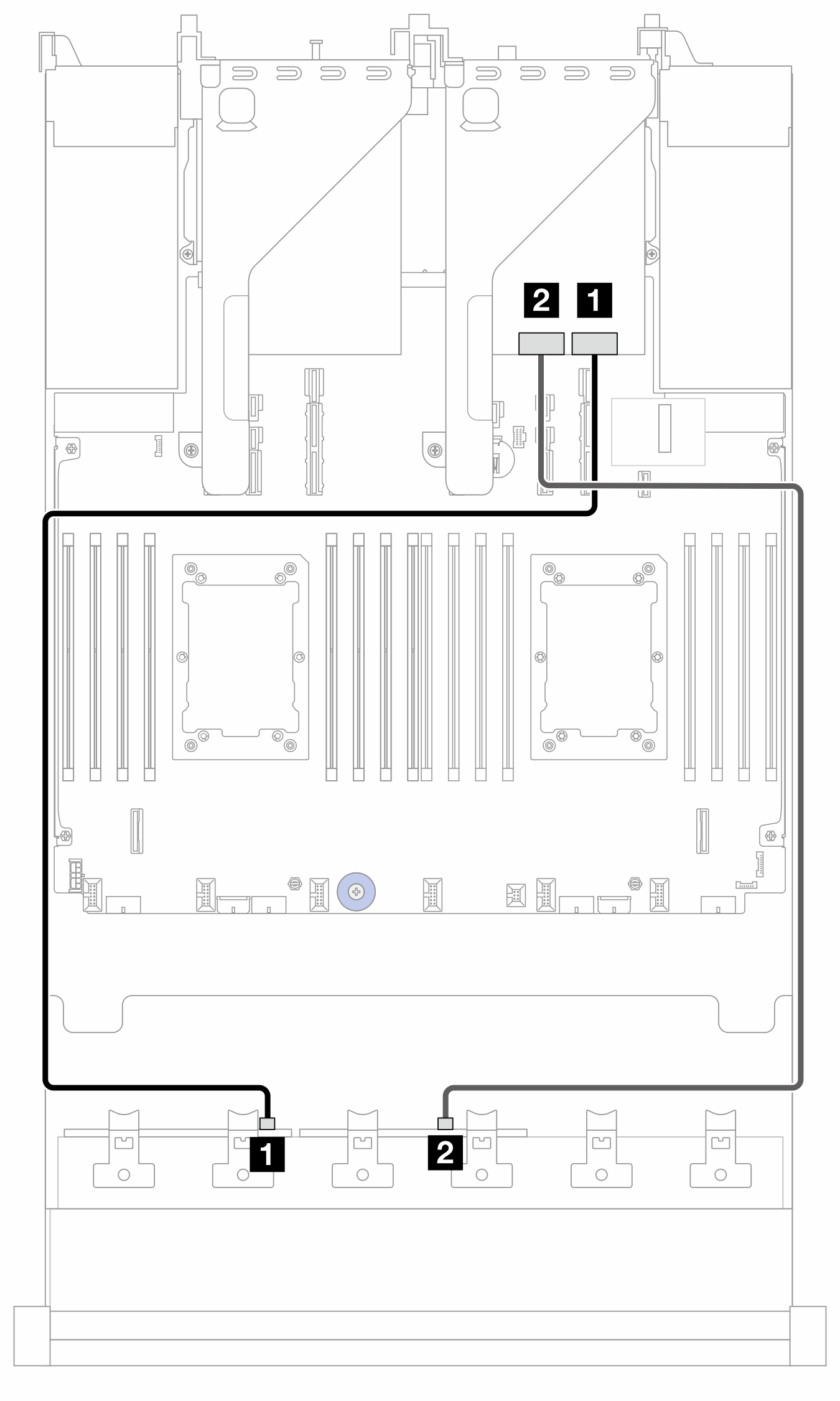
| Vom | Zu | Kabellänge | |
|---|---|---|---|
| 1 BP1: SAS | 1 8i Adapter:
| 1 16i Adapter:
| 900 mm |
| 2 BP2: SAS | 2 8i Adapter:
| 2
| 900 mm |
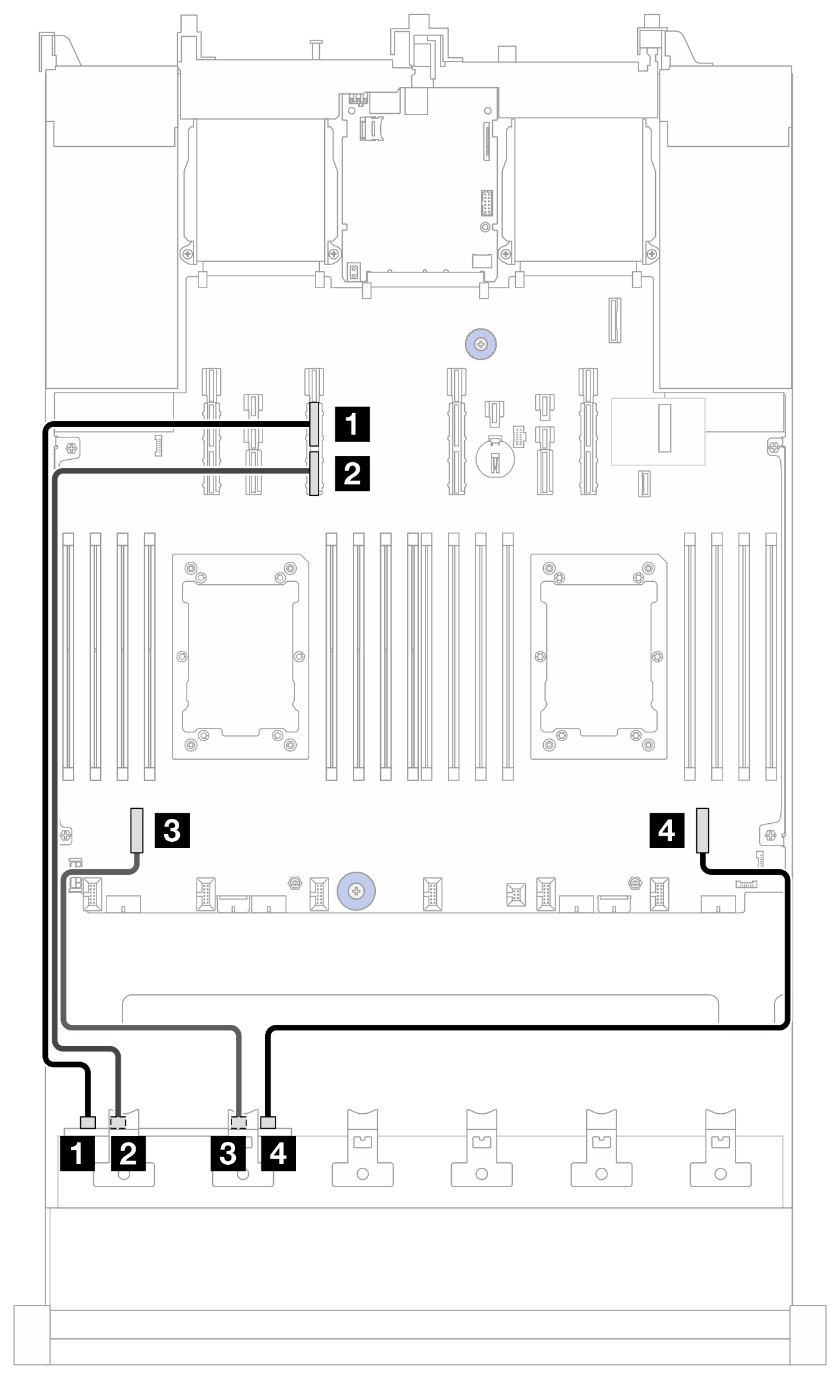
NVMe-Kabelführung (Konfiguration 8/9/10/11/12/13/14)
Anmerkung
NVMe-Kabelführung zu Rückwandplatine 1 gilt nur für Konfigurationen mit 8 x 2,5-Zoll-AnyBay oder NVMe BP1 (Konfiguration 8/9/10).
Abbildung 2. NVMe-Kabelführung zu BP1
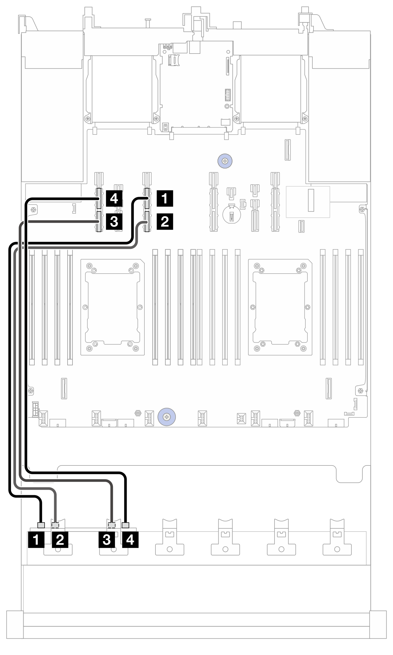
| Von (BP1) | Zu (Prozessorplatine) | Kabellänge |
|---|---|---|
| 1 NVMe 0-1 | 1 PCIe 13A | 600 mm |
| 2 NVMe 2-3 | 2 PCIe 13B | 600 mm |
| 3 NVMe 4–5 | 3 PCIe 15B | 600 mm |
| 4 NVMe 6-7 | 4 PCIe 15A | 600 mm |
Abbildung 3. NVMe-Kabelführung zu BP2
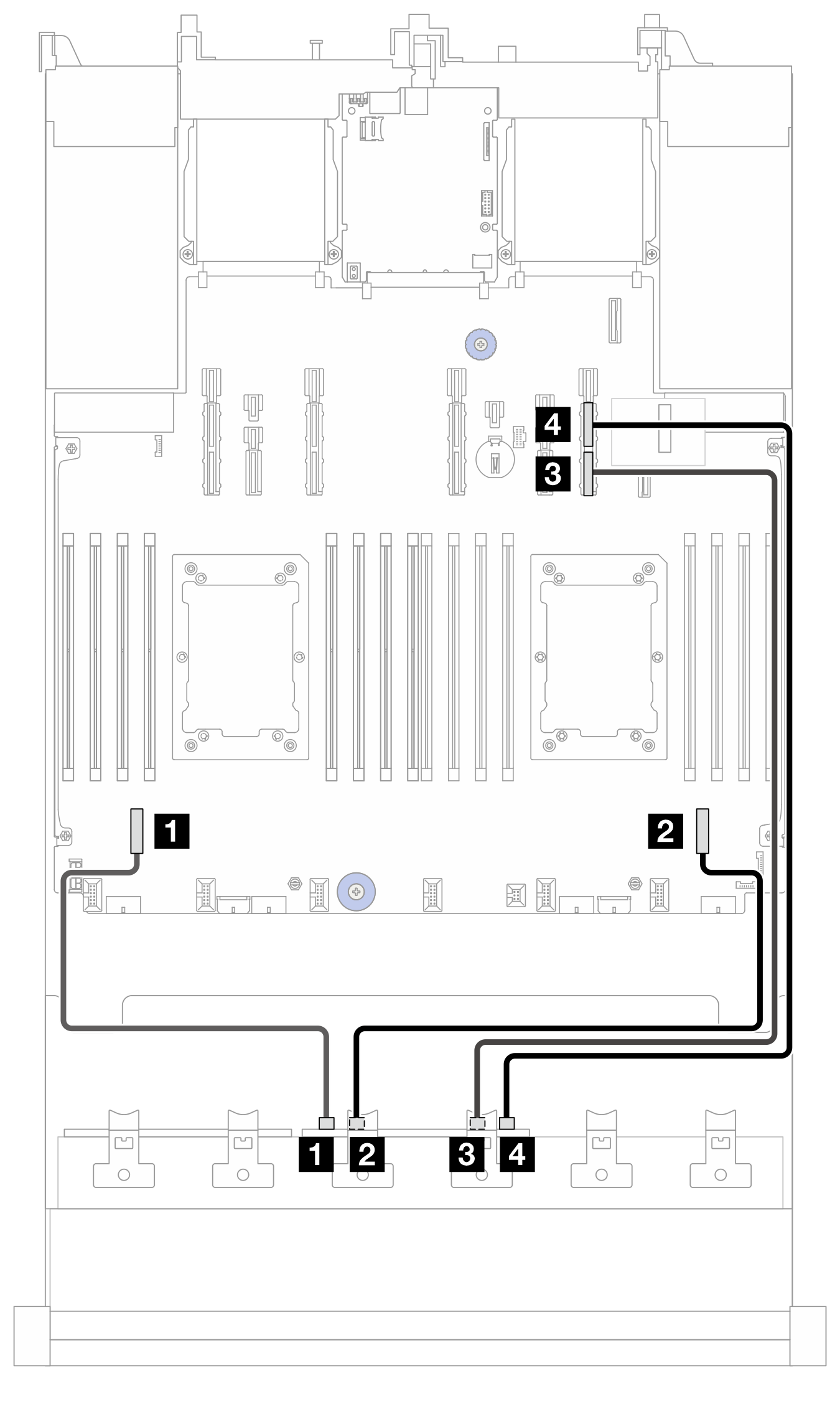
| Von (BP2) | Zu (Prozessorplatine) | Kabellänge |
|---|---|---|
| 1 NVMe 0-1 | 1 PCIe 7 | 350 mm |
| 2 NVMe 2-3 | 2 PCIe 2 | 450 mm |
| 3 NVMe 4–5 | 3 PCIe 9B | 700 mm |
| 4 NVMe 6-7 | 4 PCIe 9A | 700 mm |
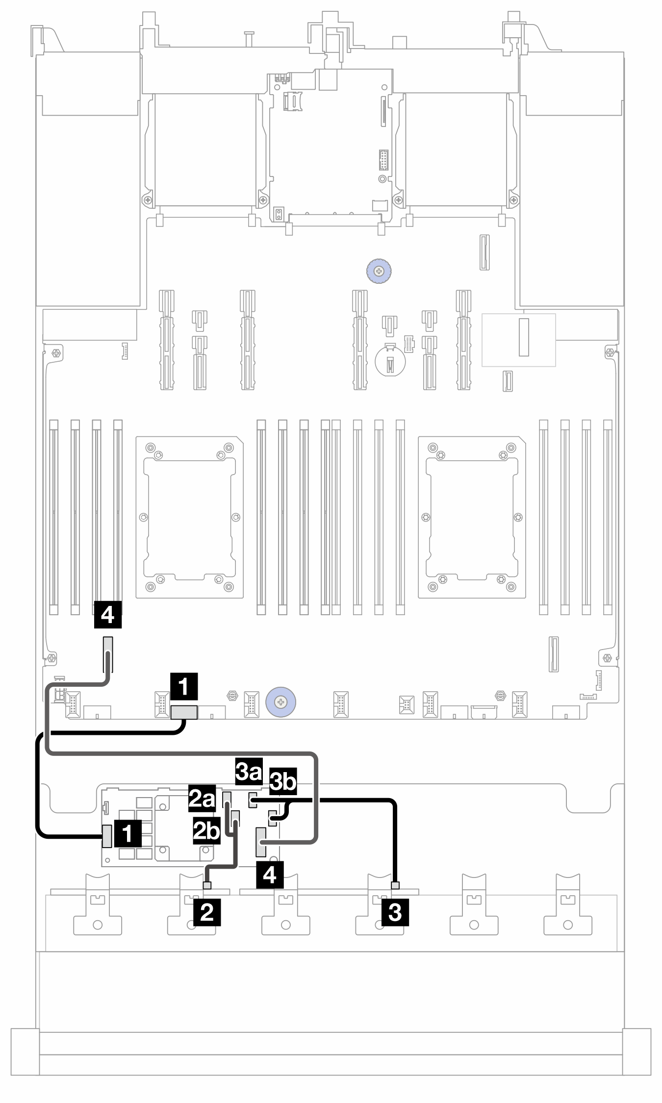
Kabelführung zum CFF 16i Adapter (Konfiguration 5/10/12/14)
Anmerkung
Kabel 3 wird nur bei Konfiguration 12 benötigt.
Abbildung 4. Kabelführung zum CFF 16i Adapter (Konfiguration 5/10/12/14)
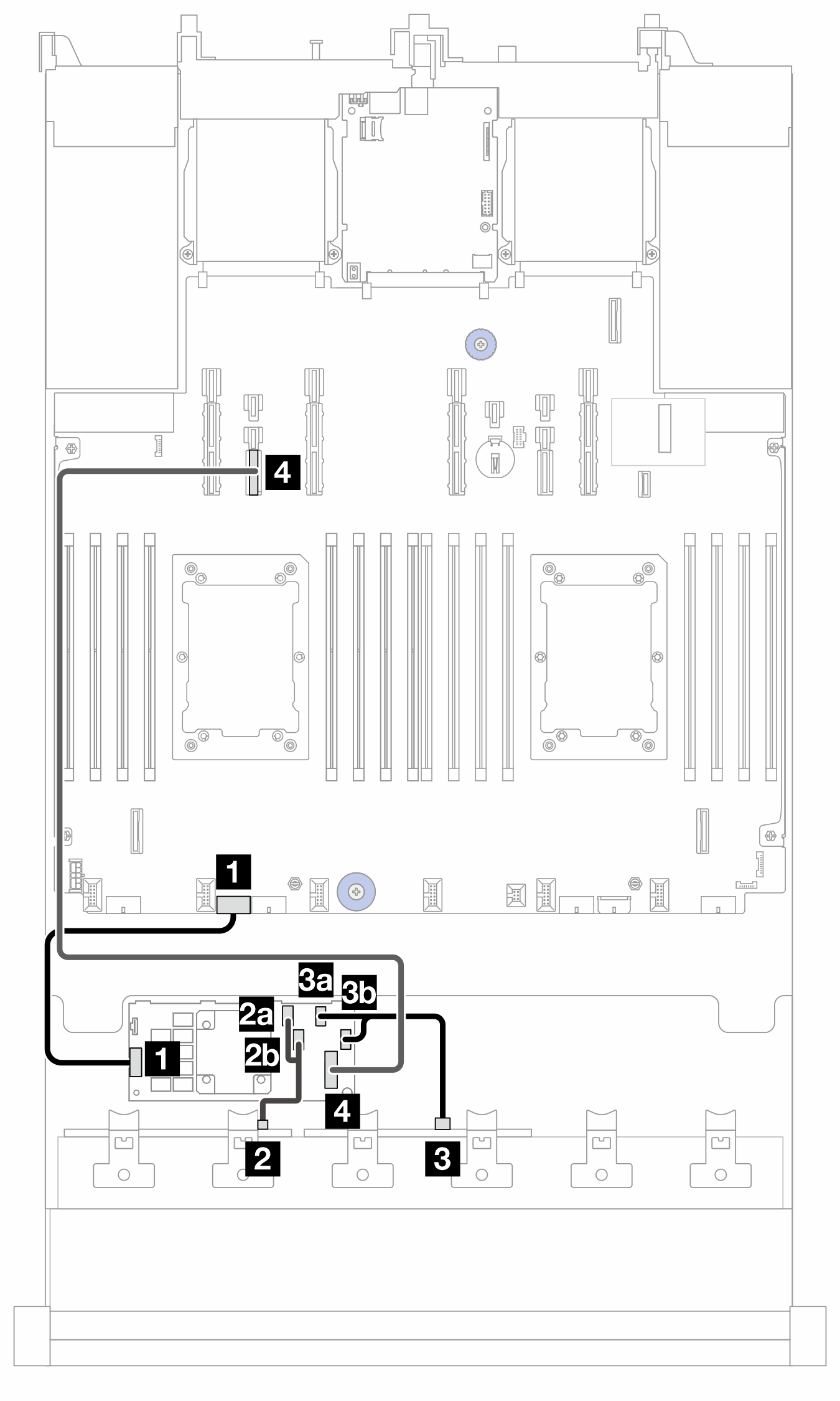
2P: zwei Prozessoren; 1P: ein Prozessor; PB: Prozessorplatine
| Von (CFF 16i Adapter) | Zu | Kabellänge |
|---|---|---|
| 1 POWER | 1 PB: RAID PWR | 210 mm |
| 2a C0 | 2 BP1: SAS | 140/140 mm |
| 2b C1 | ||
| 3a C2 | 3 BP2: SAS | 140/140 mm |
| 3b C3 | ||
| 4 MB (CFF INPUT) | 4 PB: PCIe 14 | 900 mm |
NVMe-Kabelführung (Konfiguration 3/4/5)
Abbildung 5. NVMe-Kabelführung zu BP1
| Von (BP1) | Zu (Prozessorplatine) | Kabellänge |
|---|---|---|
| 1 NVMe 0-1 | 1 PCIe 13A | 600 mm |
| 2 NVMe 2-3 | 2 PCIe 13B | 600 mm |
| 3 NVMe 4–5 | 3 PCIe 7 | 350 mm |
| 4 NVMe 6-7 | 4 PCIe 2 | 450 mm |
Kabelführung zum CFF 16i Adapter (Konfiguration 2/7)
Anmerkung
Kabel 3 wird nur bei Konfiguration 7 benötigt.
Abbildung 6. Kabelführung zum CFF 16i Adapter (Konfiguration 2/7)
2P: zwei Prozessoren; 1P: ein Prozessor; PB: Prozessorplatine
| Von (CFF 16i Adapter) | Zu | Kabellänge |
|---|---|---|
| 1 POWER | 1 PB: RAID PWR | 210 mm |
| 2a C0 | 2 BP1: SAS | 140/140 mm |
| 2b C1 | ||
| 3a C2 | 3 BP2: SAS | 140/140 mm |
| 3b C3 | ||
| 4 MB (CFF INPUT) | 4 PB: PCIe 7 | 450 mm |
Feedback geben