Vorne 24 x 2,5-Zoll-NVMe + Mitte 8 x 2,5-Zoll-NVMe + hinten 4 x 2,5-Zoll-NVMe
Dieser Abschnitt enthält Informationen zur Kabelführung für eine Konfiguration mit 24 x 2,5-Zoll-NVMe vorne + 8 x 2,5-Zoll-NVMe in der Mitte + 4 x 2,5-Zoll-NVMe hinten.
Anmerkung
Diese Konfiguration wird nur unterstützt, wenn zwei Prozessoren installiert sind.
NVMe-Kabelführung zu BP1
Abbildung 1. NVMe-Kabelführung zu BP1
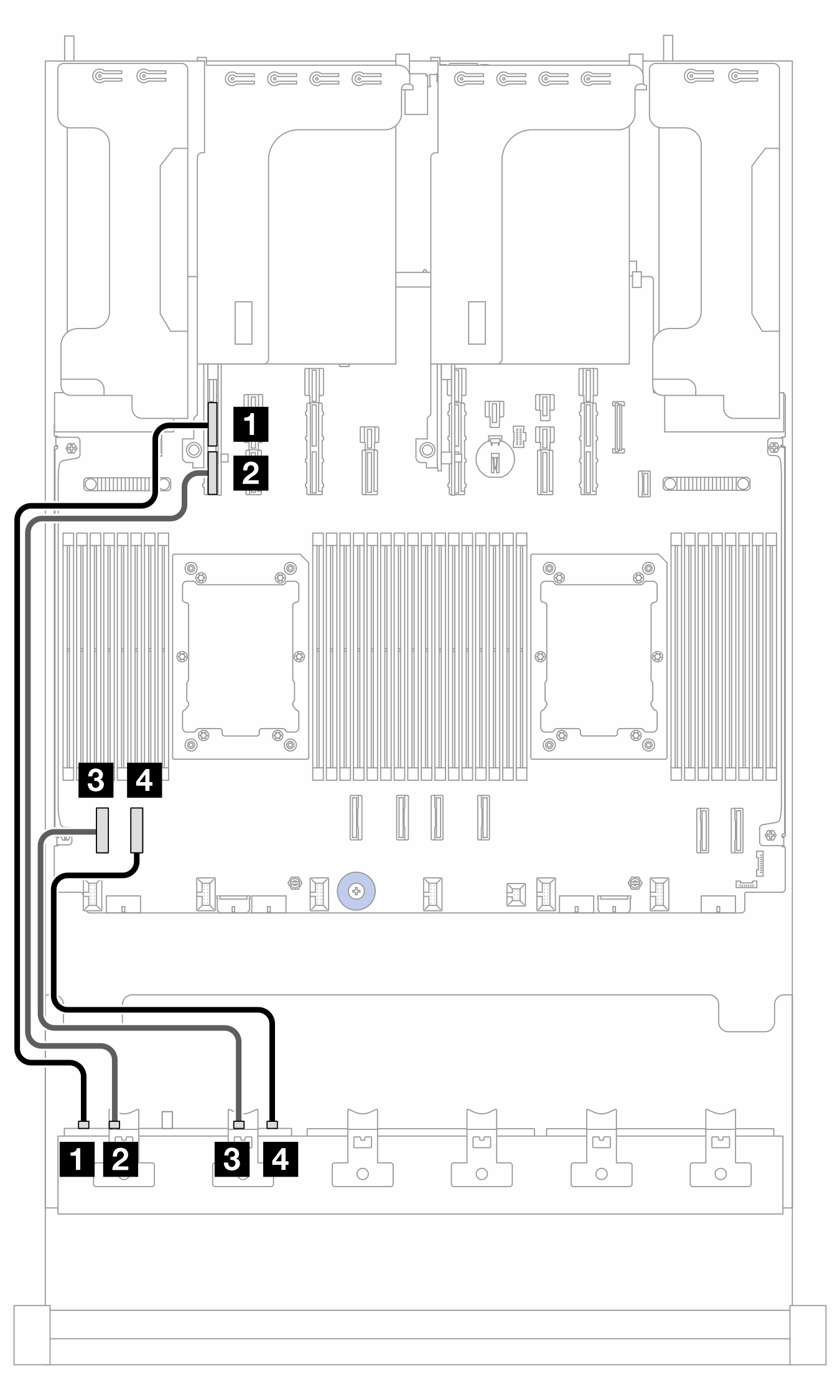
| Von (BP1) | Zu (Prozessorplatine) | Kabellänge |
|---|---|---|
| 1 NVMe 0-1 | 1 PCIe 15A | 600 mm |
| 2 NVMe 2-3 | 2 PCIe 15B | 600 mm |
| 3 NVMe 4–5 | 3 PCIe 8 | 350 mm |
| 4 NVMe 6-7 | 4 PCIe 7 | 350 mm |
NVMe-Kabelführung zu BP2
Abbildung 2. Kabelführung zu BP2
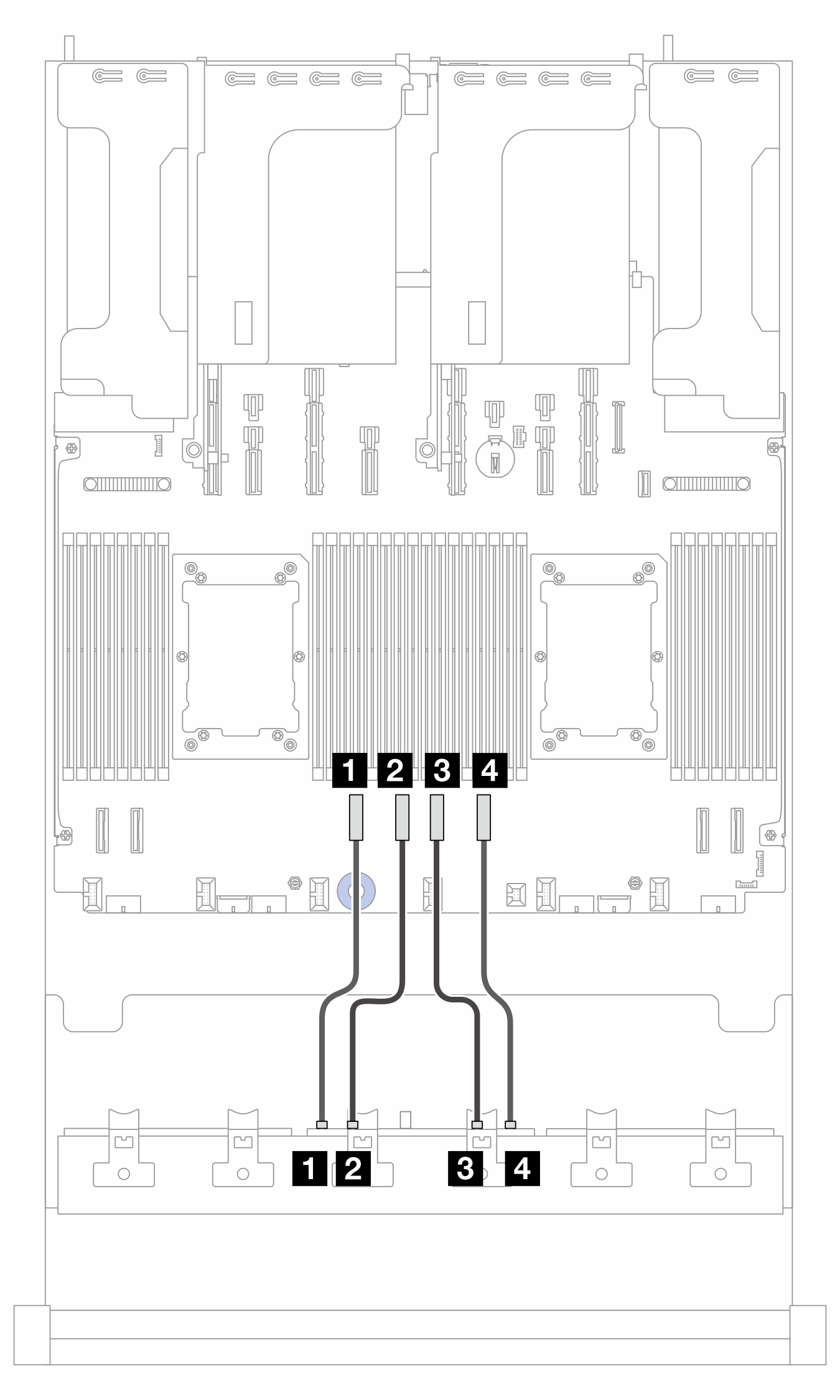
| Von (BP2) | Zu (Prozessorplatine) | Kabellänge |
|---|---|---|
| 1 NVMe 0-1 | 1 PCIe 6 | 250 mm |
| 2 NVMe 2-3 | 2 PCIe 5 | 250 mm |
| 3 NVMe 4–5 | 3 PCIe 4 | 250 mm |
| 4 NVMe 6-7 | 4 PCIe 3 | 250 mm |
NVMe-Kabelführung zu BP3
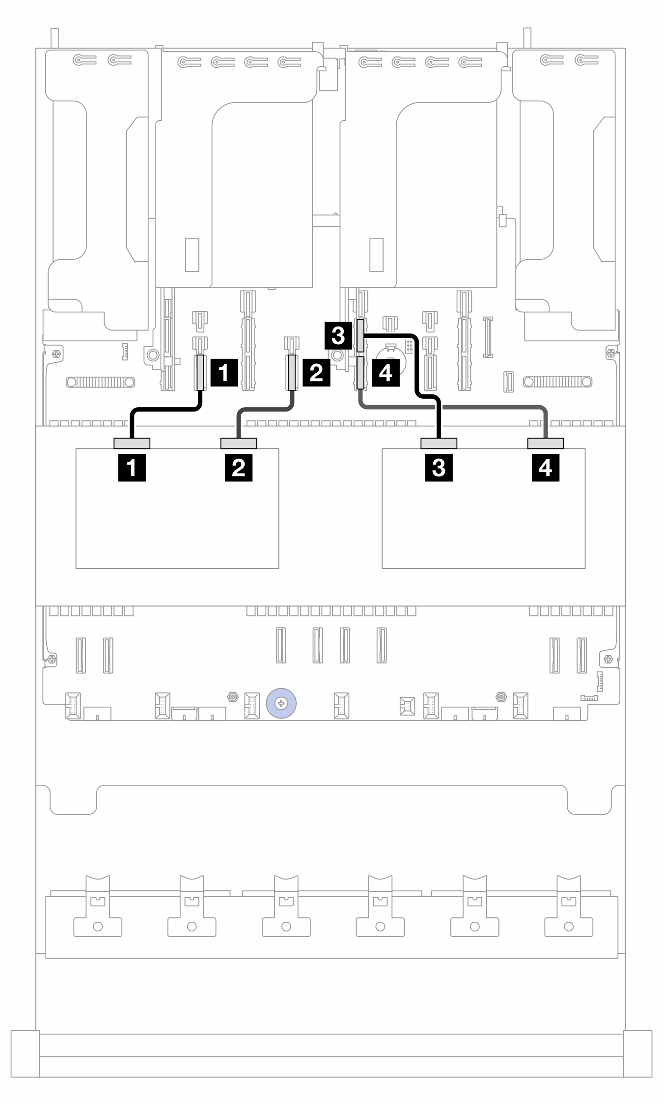
Abbildung 3. NVMe-Kabelführung zu BP3
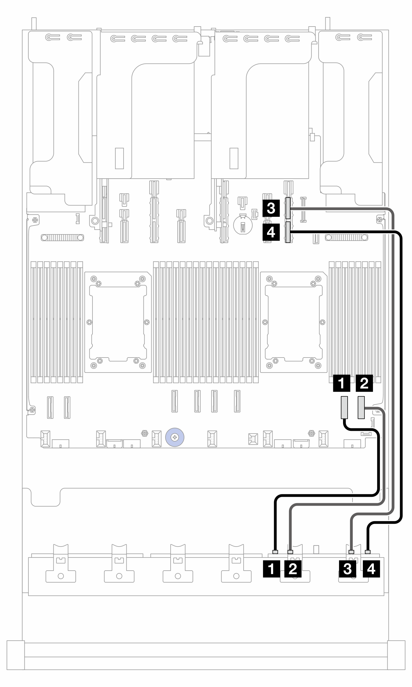
| Von (BP3) | Zu (Prozessorplatine) | Kabellänge |
|---|---|---|
| 1 NVMe 0-1 | 1 PCIe 2 | 350 mm |
| 2 NVMe 2-3 | 2 PCIe 1 | 350 mm |
| 3 NVMe 4–5 | 3 PCIe 9A | 600 mm |
| 4 NVMe 6-7 | 4 PCIe 9B | 600 mm |
NVMe-Kabelführung zu BP9
Abbildung 4. NVMe-Kabelführung zu BP9
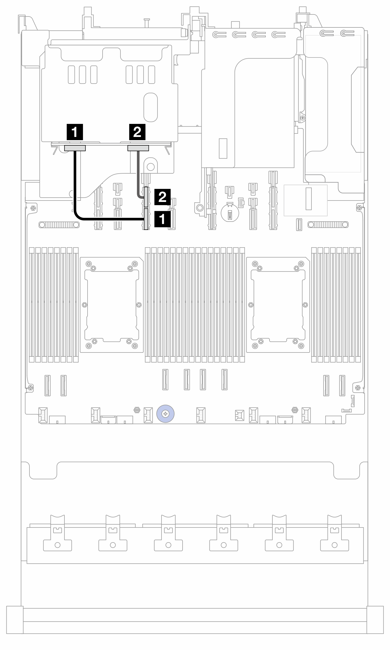
| Von (BP9) | Zu (Prozessorplatine) | Kabellänge |
|---|---|---|
| 1 NVMe 2‑3 | 1 PCIe 13B | 280 mm |
| 2 NVMe 0‑1 | 2 PCIe 13A | 280 mm |
NVMe-Kabelführung zu BP10 und BP11
Abbildung 5. NVMe-Kabelführung zu BP10 und BP11
| Von | Zu (Prozessorplatine) | Kabellänge |
|---|---|---|
| 1 BP10: NVMe 0-1 | 1 PCIe 14 | 280 mm |
| 2 BP10: NVMe 2-3 | 2 PCIe 12 | 280 mm |
| 3 BP11: NVMe 0-1 | 3 PCIe 11A | 280 mm |
| 4 BP11: NVMe 2-3 | 4 PCIe 11B | 280 mm |
Feedback geben