E3.S chassis with Compute Complex Neptune Core Module
This section provides backplane cable connection information for server models with front E3.S bays and Compute Complex Neptune Core Module.
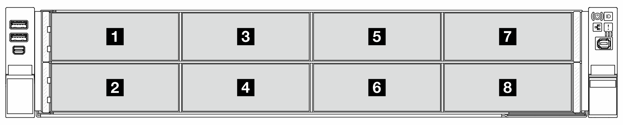
Figure 1. E3.S backplane numbering
Supported E3.S configurations
The table below lists the E3.S configurations supported by servers with Compute Complex Neptune Core Module.
Note
In the table below,
1T
denotes an E3.S hot-swap drive.When upgrading E3.S drives, make sure to follow the installation sequence provided in the table below.
BP1 | BP2 | BP3 | BP4 | BP5 | BP6 | BP7 | BP8 |
|---|---|---|---|---|---|---|---|
| Processor 2 | Processor 1 | ||||||
4x1T | 4x1T | ||||||
4x1T | 4x1T | 4x1T | 4x1T | ||||
Power cable connections
Figure 2. Power cable connections
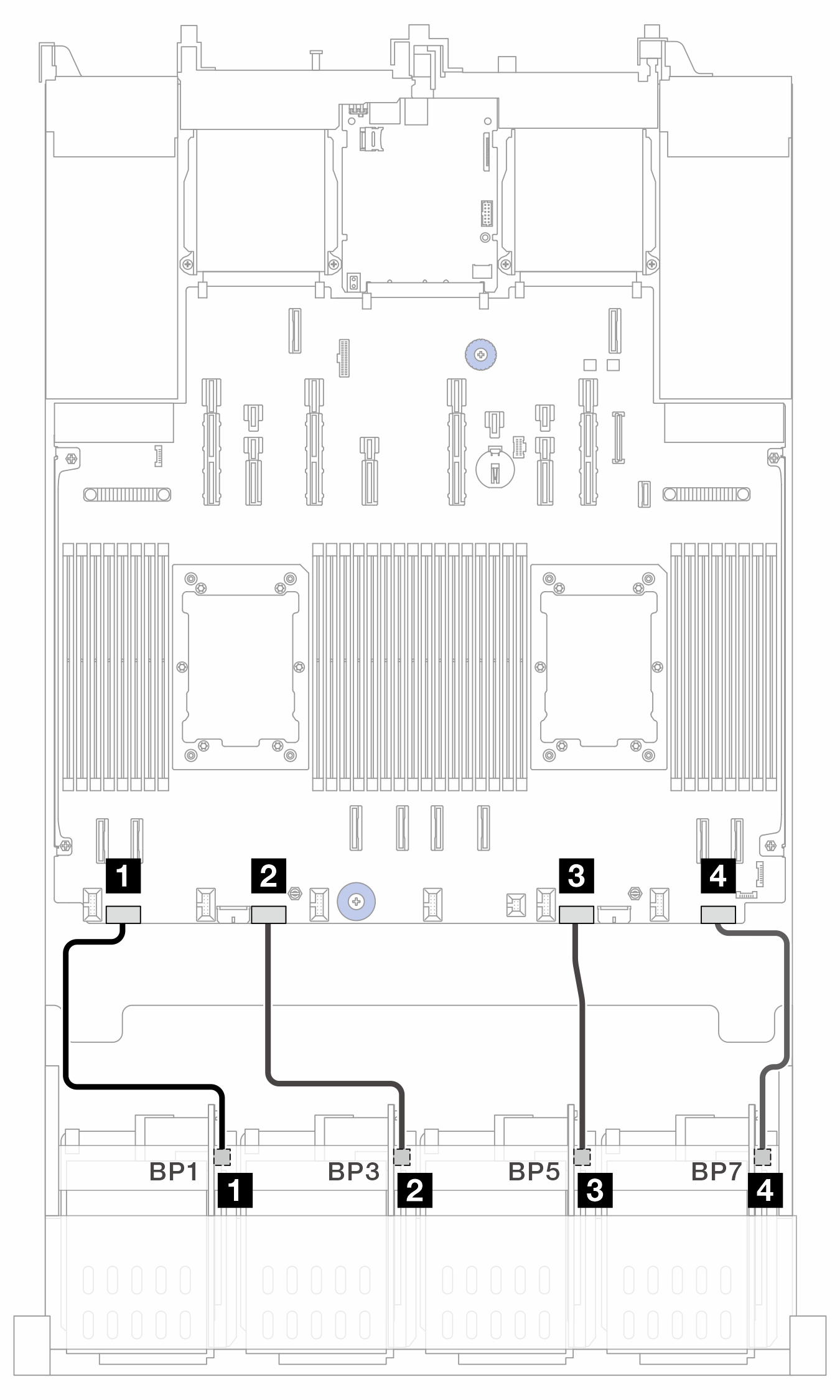
| From | To (processor board) | Cable length |
|---|---|---|
| 1 BP1: PWR | 1 PWR 1 | 250 mm |
| 2 BP3: PWR | 2 PWR 2 | 250 mm |
| 3 BP5: PWR | 3 PWR 3 | 250 mm |
| 4 BP7: PWR | 4 PWR 4 | 250 mm |
Signal cable connections
Figure 3. Signal cable connections
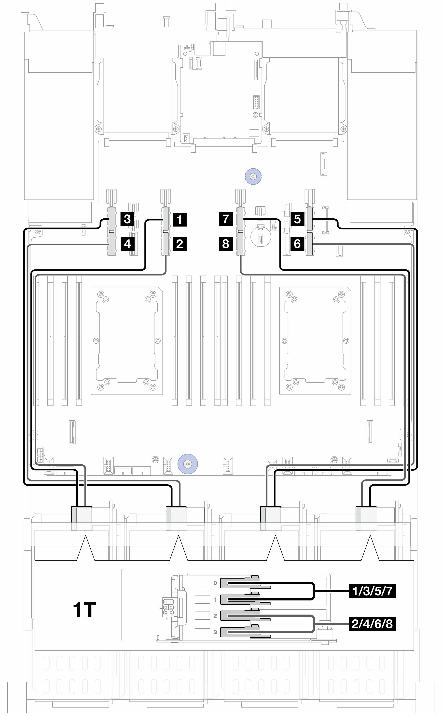
| From | To (processor board) | Cable length |
|---|---|---|
| 1 BP1: Bay 0, Bay 1 | 1 PCIe 13A | 630 mm |
| 2 BP1: Bay 2, Bay 3 | 2 PCIe 13B | 630 mm |
| 3 BP3: Bay 0, Bay 1 | 3 PCIe 15A | 630 mm |
| 4 BP3: Bay 2, Bay 3 | 4 PCIe 15B | 630 mm |
| 5 BP5: Bay 0, Bay 1 | 5 PCIe 9A | 630 mm |
| 6 BP5: Bay 2, Bay 3 | 6 PCIe 9B | 630 mm |
| 7 BP7: Bay 0, Bay 1 | 7 PCIe 11A | 630 mm |
| 8 BP7: Bay 2, Bay 3 | 8 PCIe 11B | 630 mm |
Give documentation feedback