Front 24 x 2.5" SAS/SATA + Rear 4 x 2.5" SAS/SATA
This topic provides cable routing information for the front 24 x 2.5" SAS/SATA + rear 4 x 2.5" SAS/SATA configuration.
The configuration numbers in the table below are for descriptive purposes only.
| BP config. | Storage controller | Config. No. |
|---|---|---|
| Front 24 x 2.5" SAS/SATA + Rear 4 x 2.5" SAS/SATA (BP1 + BP2 + BP3 + BP9) | SFF 16i + 2 x SFF 8i | 1 |
| 2 x SFF 16i | 2 | |
| CFF 16i + 2 x SFF 8i | 3 | |
| CFF 16i + SFF 16i | 4 | |
| CFF EXP + SFF 8i/16i | 5 | |
| CFF EXP + CFF 16i | 6 |
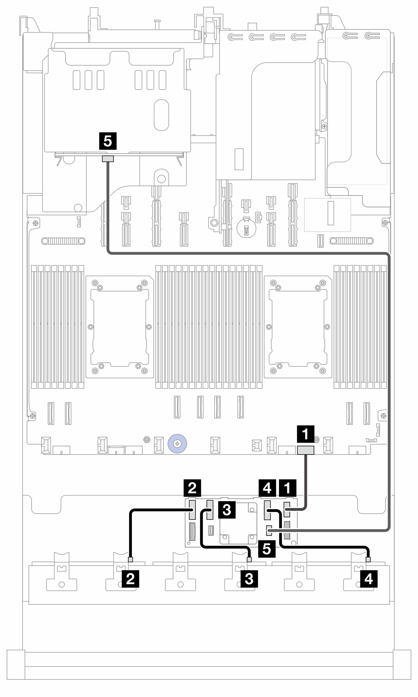
Cable routing to SFF 8i/16i adapter (config. 1/2)
Note
The location of the adapter and cable connectors on the adapter may differ from those shown in the illustration. For details, see the table below.
Figure 1. Cable routing to SFF 8i/16i adapter (config. 1/2)
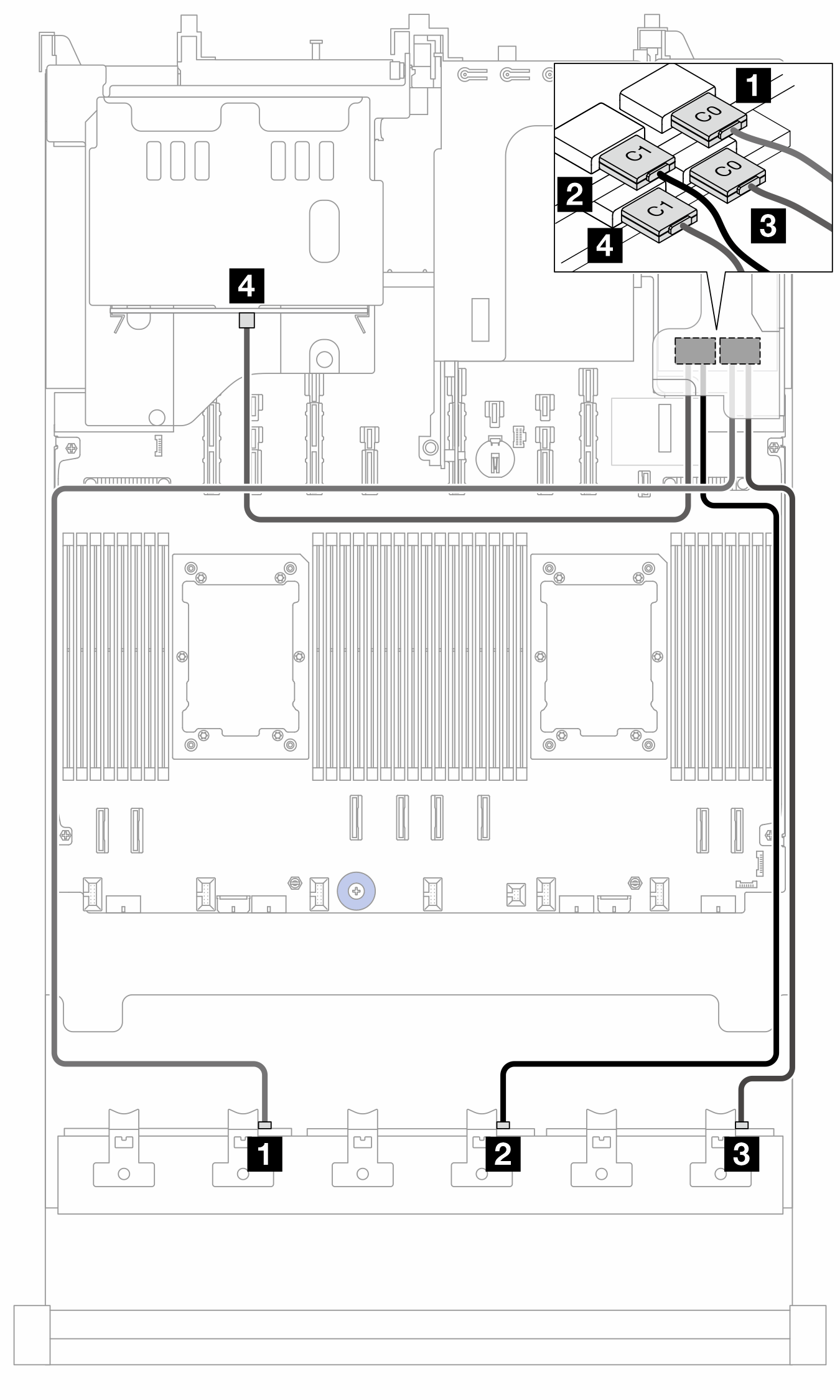
| From | To | Cable length | |
|---|---|---|---|
| Config. 1 | Config. 2 | ||
| 1 BP1: SAS | 1 16i adapter:
| 1 16i adapter:
| 900 mm |
| 2 BP2: SAS | 2
| 2
| 900 mm |
| 3 BP3: SAS | 3 8i adapter:
| 3 16i adapter:
| 900 mm |
| 4 BP9: SAS | 4 8i adapter: C0 | 4
| 450 mm |
Cable routing to SFF 8i/16i adapter (config. 3/4)
Note
The location of the adapter and cable connectors on the adapter may differ from those shown in the illustration. For details, see the table below.
Figure 2. Cable routing to SFF 8i/16i adapter (config. 3/4)
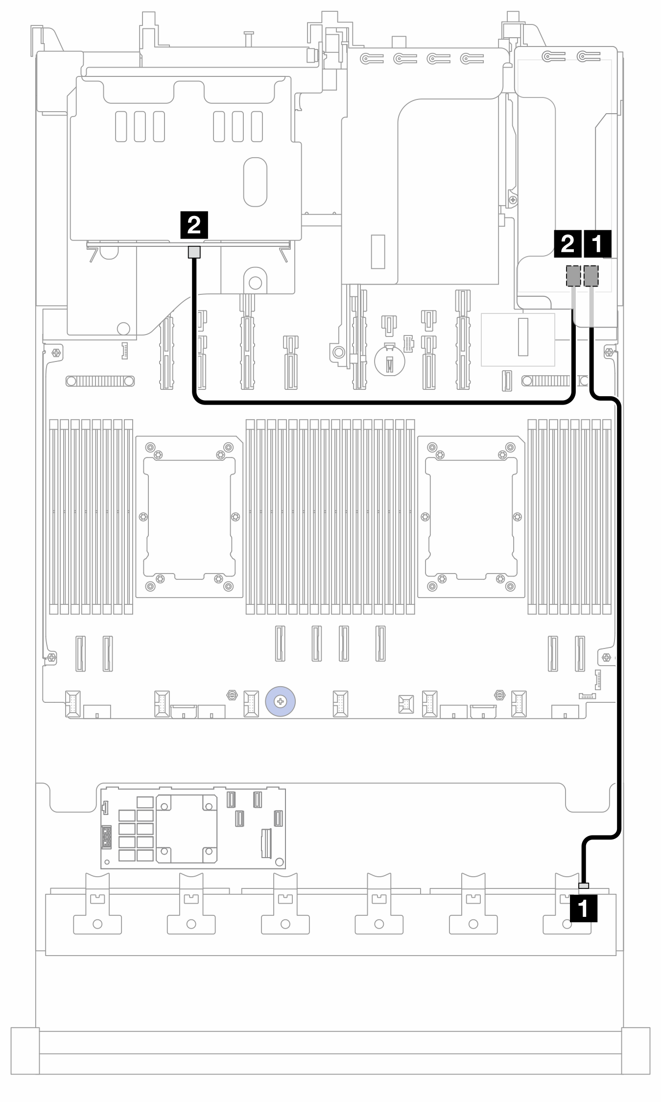
| From | To | Cable length | |
|---|---|---|---|
| Config. 3 | Config. 4 | ||
| 1 BP3: SAS | 1 8i adapter:
| 1 16i adapter:
| 900 mm |
| 2 BP9: SAS | 2 8i adapter:
| 2
| 450 mm |
Cable routing to CFF 16i adapter (config. 3/4)
Figure 3. Cable routing when two processors are installed 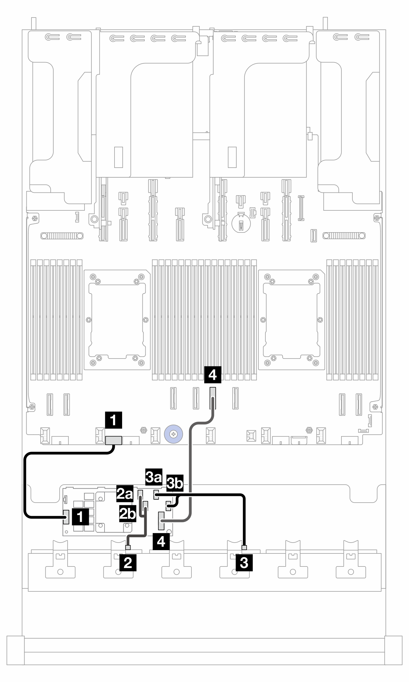 | Figure 4. Cable routing when one processor is installed 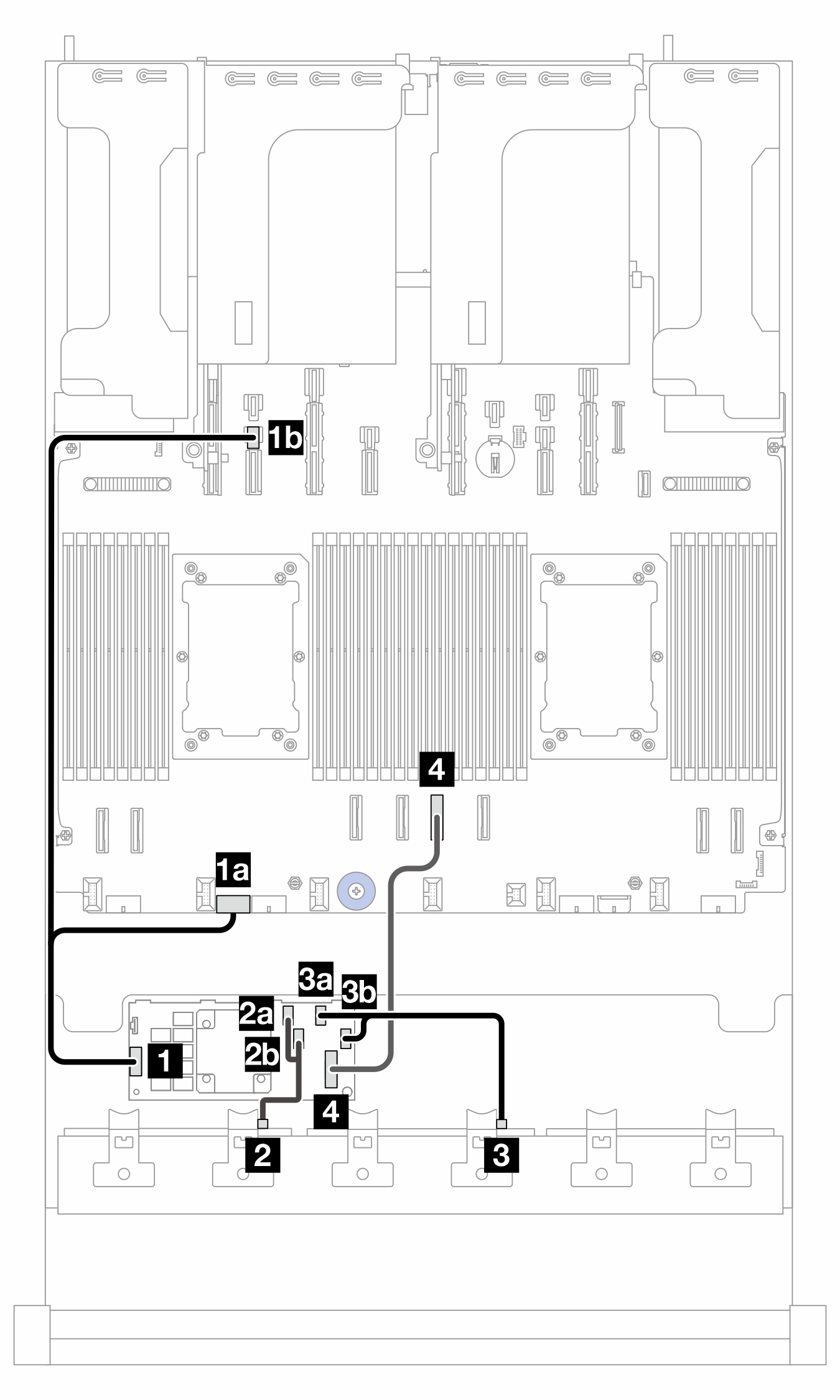 |
2P: two processors; 1P: one processor; PB: processor board
| From (CFF 16i adapter) | To | Cable length | |
|---|---|---|---|
| 2P | 1P | ||
| 1 POWER | 1 PB: RAID PWR | 1a PB: RAID PWR |
|
| 1b PB: PWR 14 | |||
| 2a C0 | 2 BP1: SAS | 2 BP1: SAS | 140/140 mm |
| 2b C1 | |||
| 3a C2 | 3 BP2: SAS | 3 BP2: SAS | 140/140 mm |
| 3b C3 | |||
| 4 MB (CFF INPUT) | 4 PB: PCIe 4 | 4 PB: PCIe 4 | 450 mm |
Cable routing to CFF expander (config. 5/6)
Figure 5. Cable routing to CFF expander
| From (CFF expander) | To | Cable length |
|---|---|---|
| 1 POWER | 1 PB: EXP PWR | 210 mm |
| 2 C0 | 2 BP1: SAS | 200 mm |
| 3 C1 | 3 BP2: SAS | 110 mm |
| 4 C2 | 4 BP3: SAS | 110 mm |
| 5 C4 | 5 BP9: SAS | 800 mm |
Cable routing to SFF 8i/16i adapter (config. 5)
Note
The location of the adapter and cable connectors on the adapter may differ from those shown in the illustration. For details, see the table below.
Figure 6. Cable routing to SFF 8i/16i adapter (config. 5)
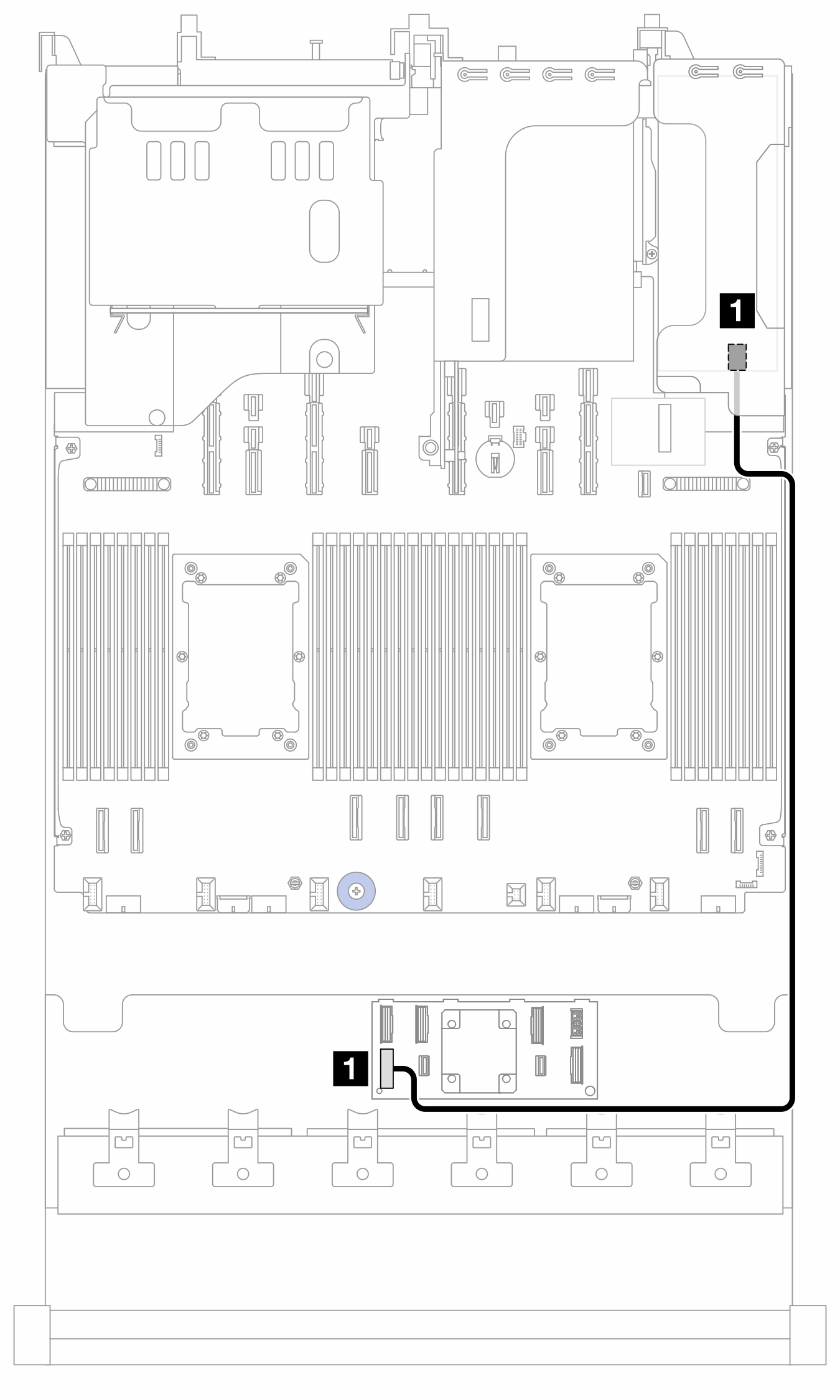
| From | To | Cable length |
|---|---|---|
| 1 CFF expander: RAID/HBA | 1 8i/16i adapter:
| 780 mm |
Cable routing to CFF 16i adapter (config. 6)
Figure 7. Cable routing when two processors are installed 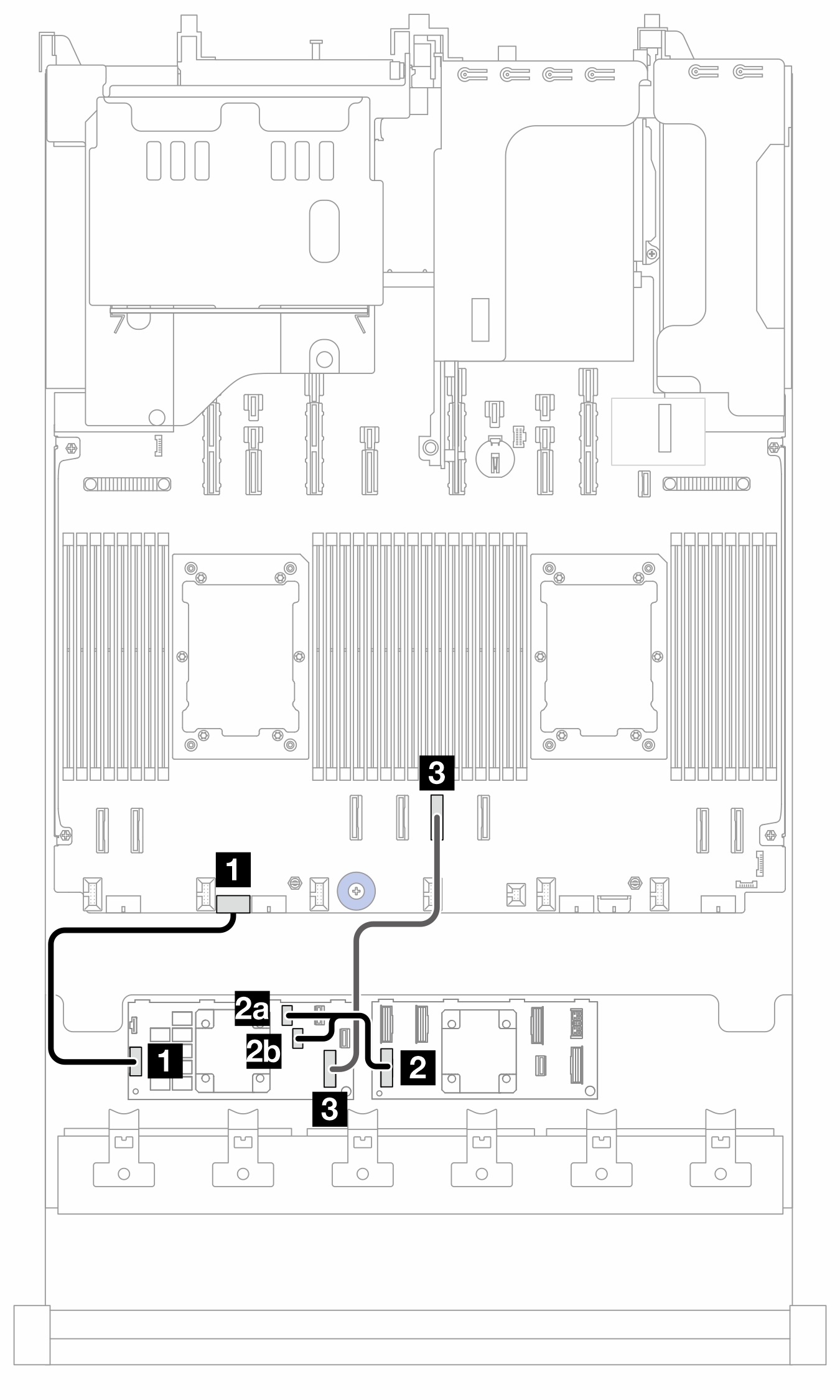 | Figure 8. Cable routing when one processor is installed 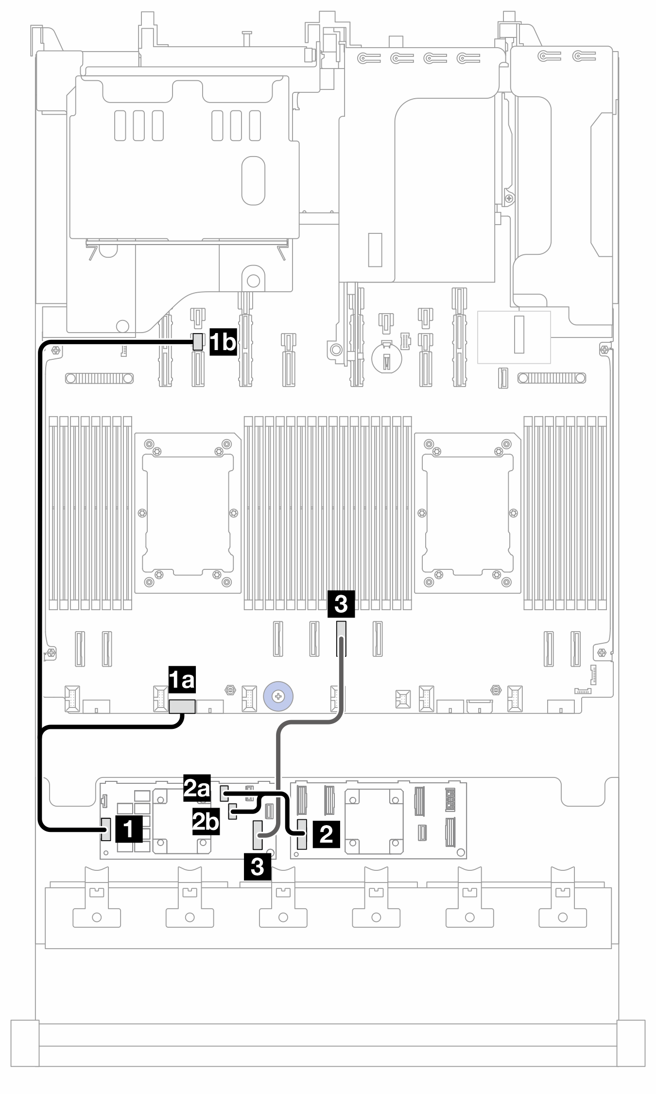 |
2P: two processors; 1P: one processor; PB: processor board
| From (CFF 16i adapter) | To | Cable length | |
|---|---|---|---|
| 2P | 1P | ||
| 1 POWER | 1 PB: RAID PWR | 1a PB: RAID PWR |
|
| 1b PB: PWR 14 | |||
| 2a C0 | 2 CFF expander: RAID/HBA | 2 CFF expander: RAID/HBA | 150/150 mm |
| 2b C1 | |||
| 3 MB (CFF INPUT) | 3 PB: PCIe 4 | 3 PB: PCIe 4 | 450 mm |
Give documentation feedback