Install the front M.2 drive cage and drive backplanes
Follow the instructions in this section to install the front M.2 drive cage and drive backplanes.
About this task
Attention
Read Installation Guidelines and Safety inspection checklist to ensure that you work safely.
Power off the server and peripheral devices and disconnect the power cords and all external cables. See Power off the server.
Prevent exposure to static electricity, which might lead to system halt and loss of data, by keeping static-sensitive components in their static-protective packages until installation, and handling these devices with an electrostatic-discharge wrist strap or other grounding system.
Note
The M.2 drive backplanes shown in the illustrations are for reference only and may differ from your actual hardware.
Figure 1. Front M.2 drive backplanes
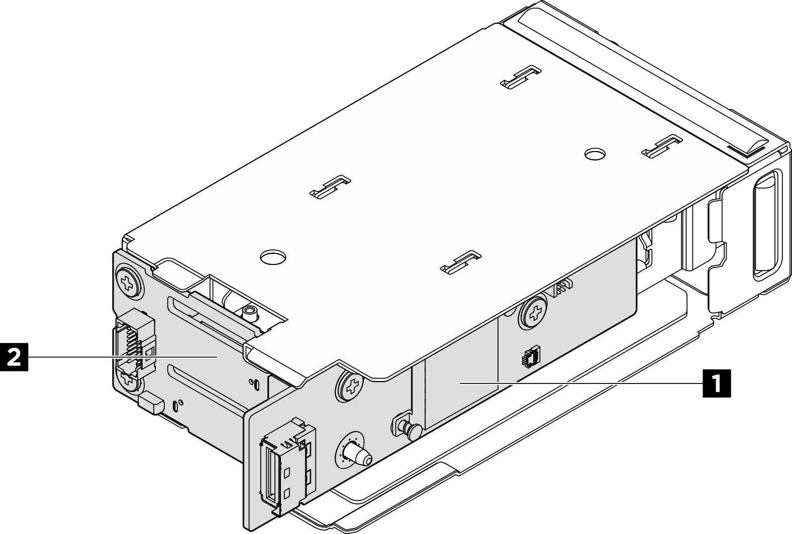
| 1 M.2 controller board | 2 M.2 boot backplane |
Procedure
- Install the M.2 boot backplane to the drive cage.
- Install the backplane.
 Insert the right side of the backplane to the drive cage.
 Pivot the left side of the backplane toward the drive cage.Figure 2. Installing the M.2 boot backplane
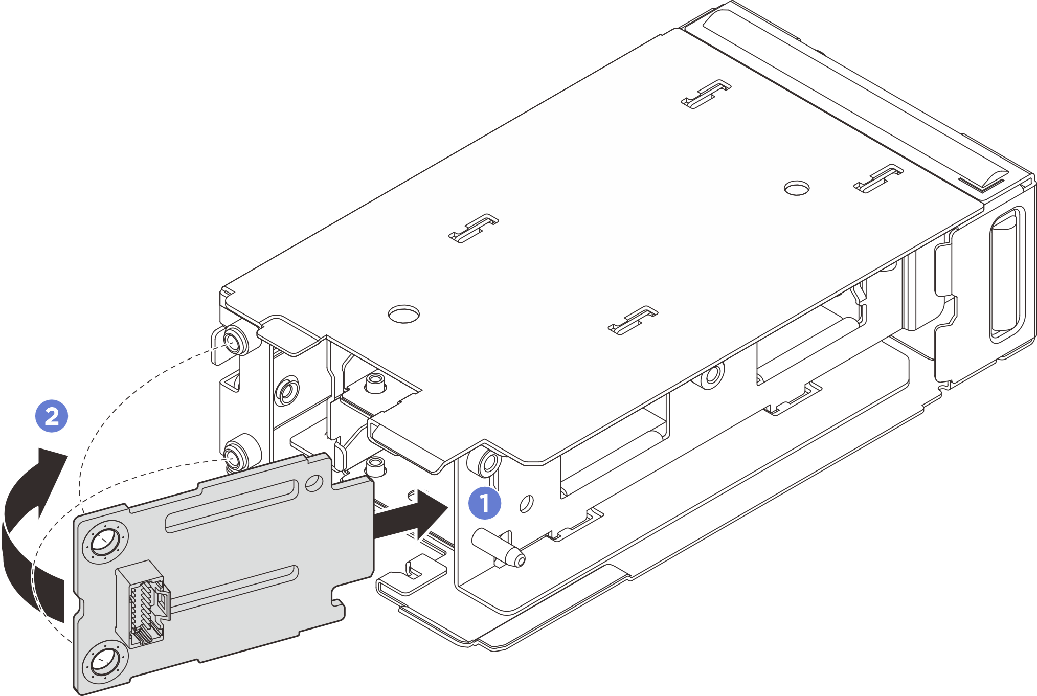
- Fasten two screws to secure the backplane.Figure 3. Fastening the screws

- Install the backplane.
- Install the M.2 controller board to the drive cage.
- Install the controller board to the drive cage. Make sure that the boot backplane contacts are fully seated in the connector on the controller board as illustrated.
- Fasten two screws to secure the controller board.
Figure 4. Installing the front M.2 controller board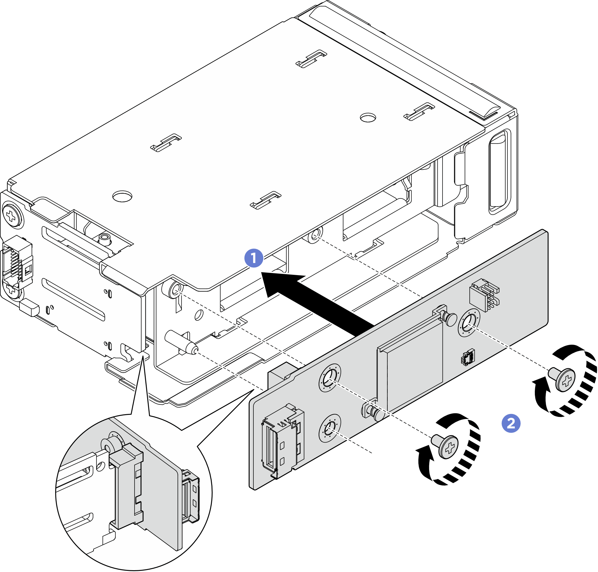
- Install the front M.2 drive cage.
- For configurations with 2.5-inch drives at front of the server, slide the front M.2 drive cage into the chassis until it clicks into place.
- For configurations with E3.S drives or CXL memory modules (CMMs), slide the front M.2 drive cage into the frame until it clicks into place.
Figure 5. Installing the front M.2 drive cage into the chassis Figure 6. Installing the front M.2 drive cage into the cage frame
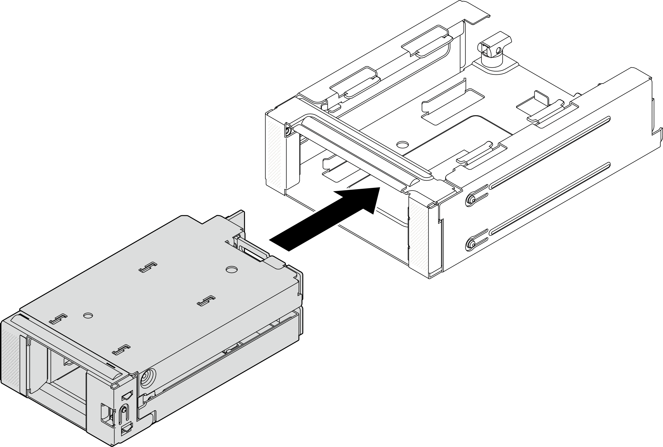
- For configurations with E3.S drives or CMMs, install the front M.2 drive cage with cage frame into the chassis.
- Make sure that the latch is in the open position.
- Slide the drive cage with frame into the chassis until the guide pin on the chassis is seated into place.
 Press the latch down to secure the drive cage with frame.
Figure 7. Installing the front M.2 drive cage with frame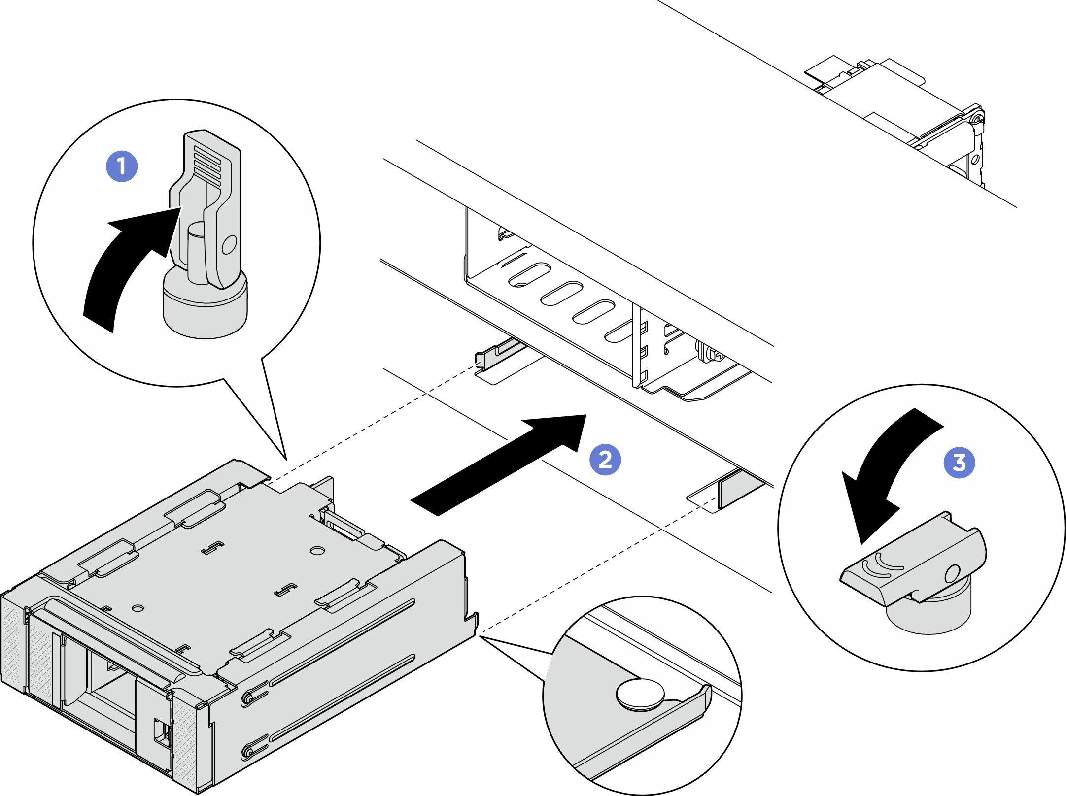
Give documentation feedback