Memory module installation rules and order
Memory modules must be installed in a specific order based on the memory configuration that you implement and the number of processors and memory modules installed in the server.
Supported memory types
For information on the types of memory module supported by this server, see Memory section in Technical Specifications.
For a list of supported memory options, see Lenovo ServerProven website.
Information about optimizing memory performance and configuring memory is available at the Lenovo Press website:
In addition, you can take advantage of a memory configurator, which is available at the following site:
Lenovo Enterprise Solutions Configurator (Memory Configurations)
Specific information about the required installation order of memory modules in your server based on the system configuration and memory mode that you are implementing is shown below.
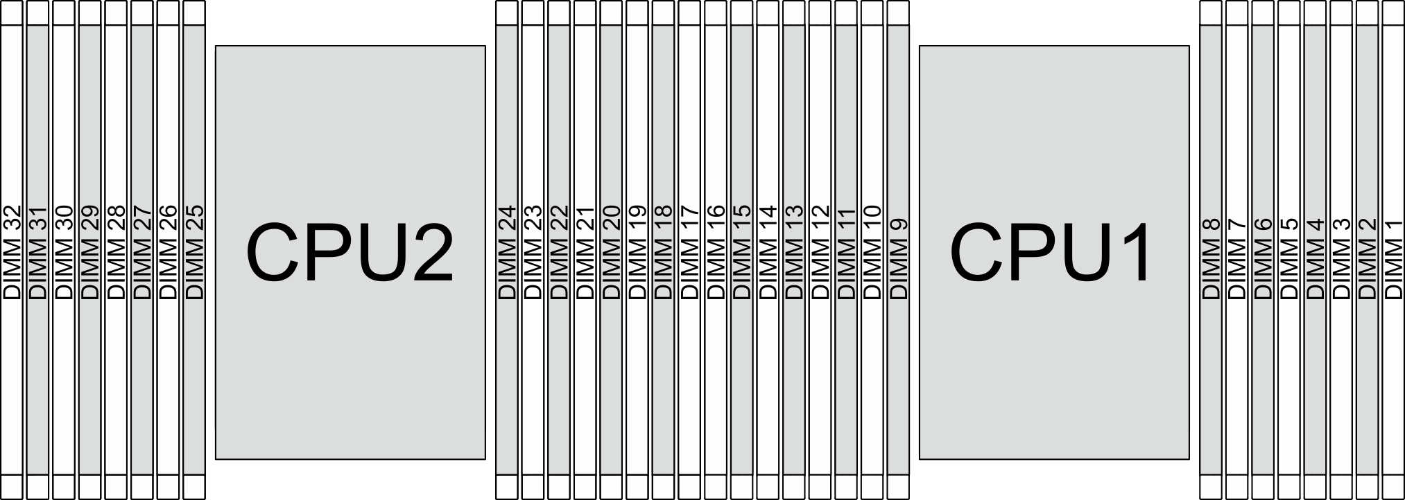
Memory modules and processors layout of servers without Compute Complex Neptune Core Module
The following illustration helps you to locate the memory module slots on the processor board for servers without Compute Complex Neptune Core Module. The memory-channel identification table below shows the relationship between the processors, memory controllers, memory channels, and memory module slot numbers.
| Processor | CPU 1 | |||||||||||||||
| Controller | iMC7 | iMC6 | iMC5 | iMC4 | iMC0 | iMC1 | iMC2 | iMC3 | ||||||||
| Channel | CH7 | CH6 | CH5 | CH4 | CH0 | CH1 | CH2 | CH3 | ||||||||
| Slot No. | 0 | 1 | 0 | 1 | 0 | 1 | 0 | 1 | 1 | 0 | 1 | 0 | 1 | 0 | 1 | 0 |
| DIMM No. | 16 | 15 | 14 | 13 | 12 | 11 | 10 | 9 | 8 | 7 | 6 | 5 | 4 | 3 | 2 | 1 |
| Processor | CPU 2 | |||||||||||||||
| Controller | iMC7 | iMC6 | iMC5 | iMC4 | iMC0 | iMC1 | iMC2 | iMC3 | ||||||||
| Channel | CH7 | CH6 | CH5 | CH4 | CH0 | CH1 | CH2 | CH3 | ||||||||
| Slot No. | 0 | 1 | 0 | 1 | 0 | 1 | 0 | 1 | 1 | 0 | 1 | 0 | 1 | 0 | 1 | 0 |
| DIMM No. | 32 | 31 | 30 | 29 | 28 | 27 | 26 | 25 | 24 | 23 | 22 | 21 | 20 | 19 | 18 | 17 |
Slot No.: DIMM slot number in each memory channel. Each memory channel has two DIMM slots: slot 0 (further from the processor) and slot 1 (closer to the processor).
DIMM No.: DIMM slot number on the processor board. Each processor has 16 DIMM slots.
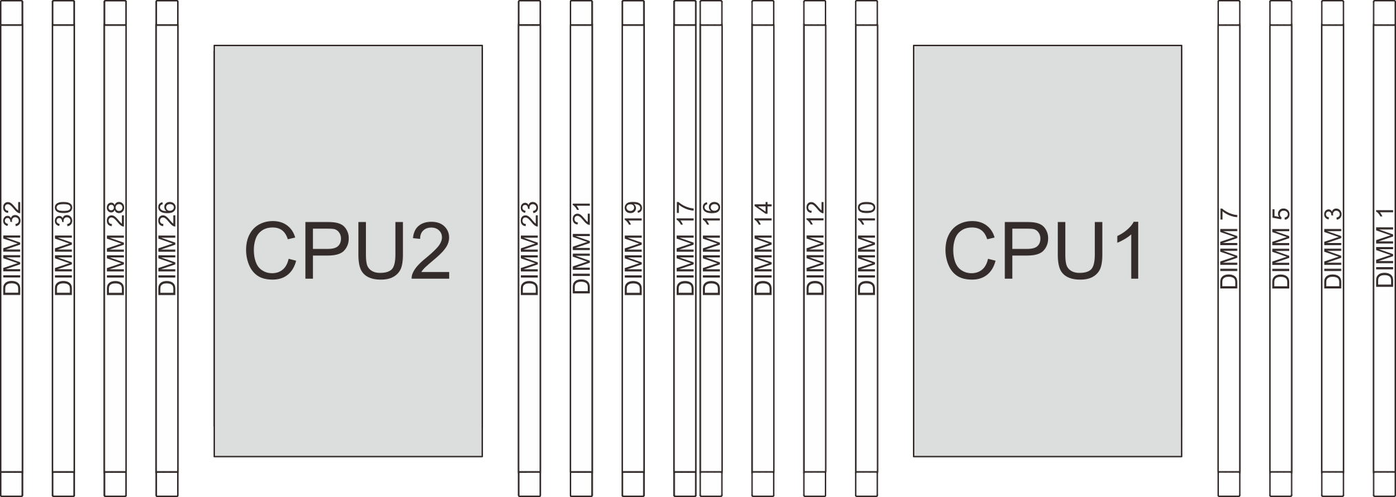
Memory modules and processors layout of servers with Compute Complex Neptune Core Module
The following illustration helps you to locate the memory module slots on the processor board for of servers with Compute Complex Neptune Core Module. The memory-channel identification table below shows the relationship between the processors, memory controllers, memory channels, and memory module slot numbers.
| Processor | CPU 1 | |||||||
| Controller | iMC7 | iMC6 | iMC5 | iMC4 | iMC0 | iMC1 | iMC2 | iMC3 |
| Channel | CH7 | CH6 | CH5 | CH4 | CH0 | CH1 | CH2 | CH3 |
| Slot No. | 0 | 0 | 0 | 0 | 0 | 0 | 0 | 0 |
| DIMM No. | 16 | 14 | 12 | 10 | 7 | 5 | 3 | 1 |
| Processor | CPU 2 | |||||||
| Controller | iMC7 | iMC6 | iMC5 | iMC4 | iMC0 | iMC1 | iMC2 | iMC3 |
| Channel | CH7 | CH6 | CH5 | CH4 | CH0 | CH1 | CH2 | CH3 |
| Slot No. | 0 | 0 | 0 | 0 | 0 | 0 | 0 | 0 |
| DIMM No. | 32 | 30 | 28 | 26 | 23 | 21 | 19 | 17 |
Slot No.: DIMM slot number in each memory channel. Each memory channel has one DIMM slot.
DIMM No.: DIMM slot number on the processor board. Each processor has eight DIMM slots.
Memory module installation guideline
At least one DIMM is required for each processor. Install at least eight DIMMs per processor for good performance.
When you replace a DIMM, the server provides automatic DIMM enablement capability without requiring you to use the Setup Utility to enable the new DIMM manually.
- For memory module installation rules and orders, see: