Remove the front PCIe adapter and riser card
Follow instructions in this section to remove the front PCIe adapter and riser 5 card.
About this task
Read Installation Guidelines and Safety inspection checklist to ensure that you work safely.
Power off the server and peripheral devices and disconnect the power cords and all external cables. See Power off the server.
Prevent exposure to static electricity, which might lead to system halt and loss of data, by keeping static-sensitive components in their static-protective packages until installation, and handling these devices with an electrostatic-discharge wrist strap or other grounding system.
Before you remove any component of a RAID array (drive, RAID card, etc.), back up all RAID configuration information.
Procedure
- Remove the front adapter assembly.NoteThe number of cables varies according to the configuration.Figure 1. Removing the front adapter assembly
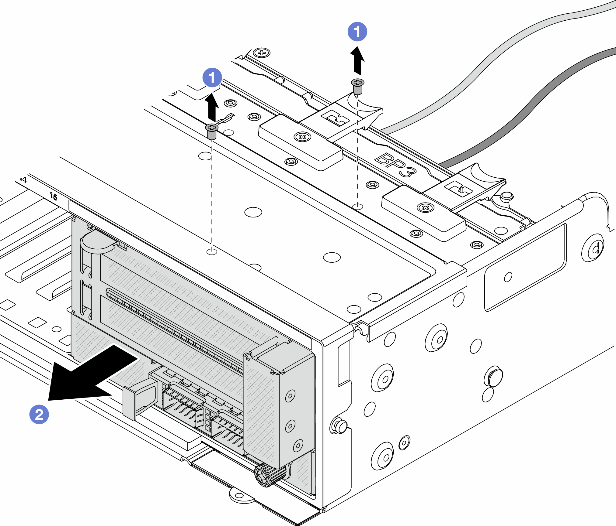
 Remove the screws that secure the assembly.
 Slide the assembly out of the front chassis.
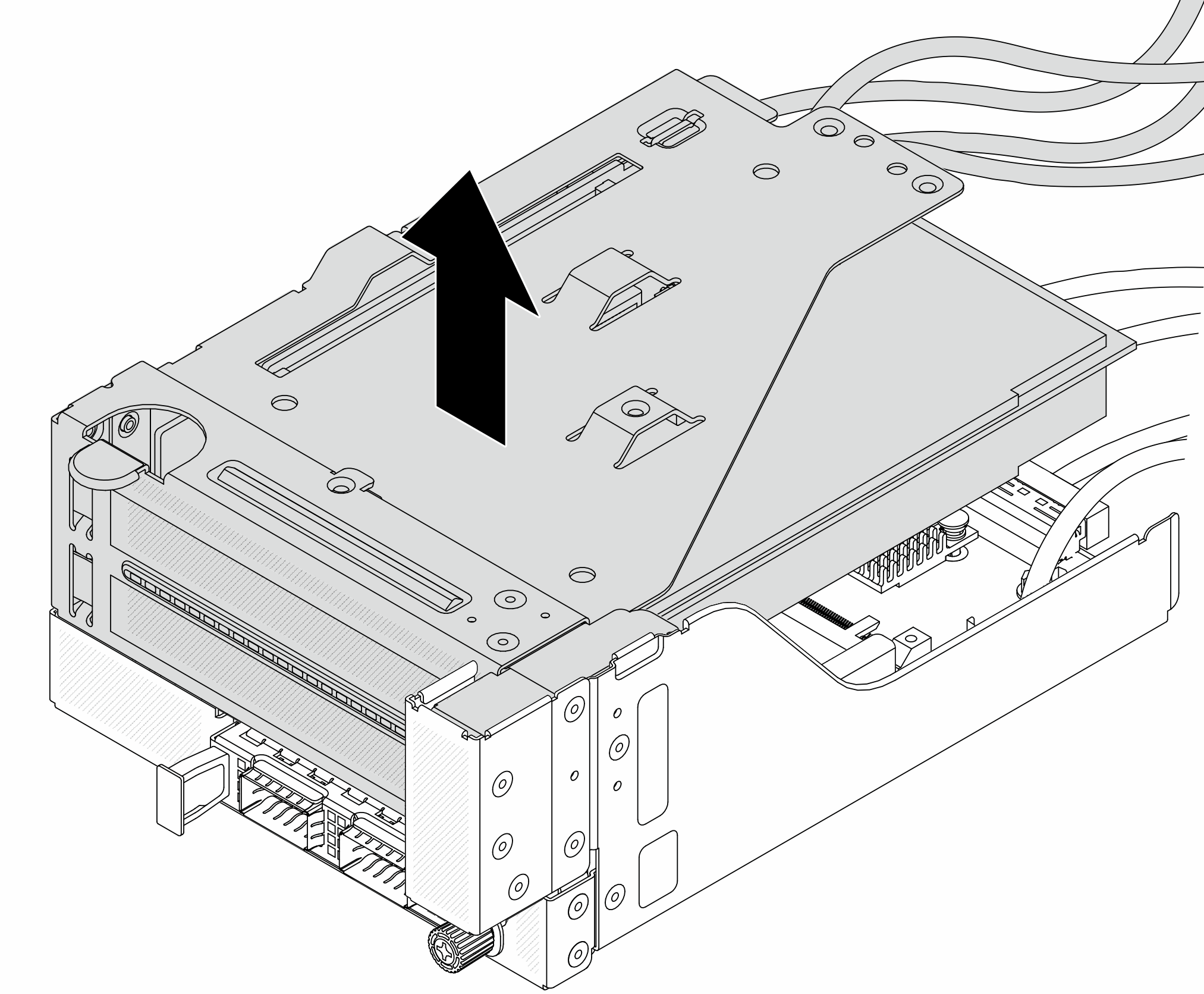
- Lift the riser 5 assembly up off the front OCP assembly, and disconnect cables from the front OCP interposer card.Figure 2. Lifting the riser 5 assembly
- Remove the PCIe adapter from the riser 5 cage.NoteIf you are removing the
ThinkSystem AMD X3522 10/25GbE DSFP28 2-port PCIe Ethernet Adapter, remove the screw that secures the adapter first. Figure 3. Removing the PCIe adapter from the riser 5 cage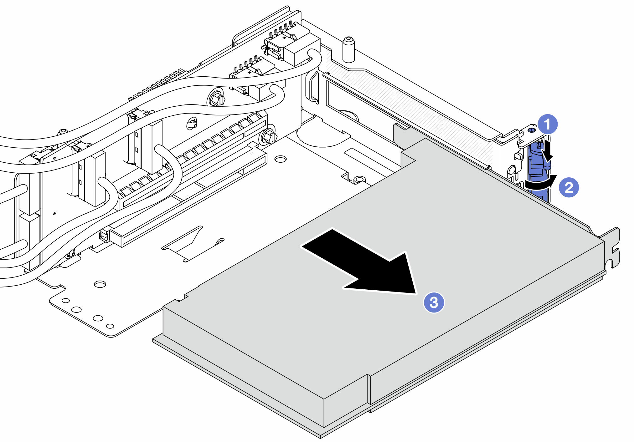
- Press the retainer clip downward.
- Rotate the retention latch to the open position.
 Grasp the PCIe adapter by its edges and carefully pull it out of the PCIe slot.
- Disconnect the cables from the riser card, and remove the riser card from the riser 5 cage.Figure 4. Removing the riser card from the riser 5 cage
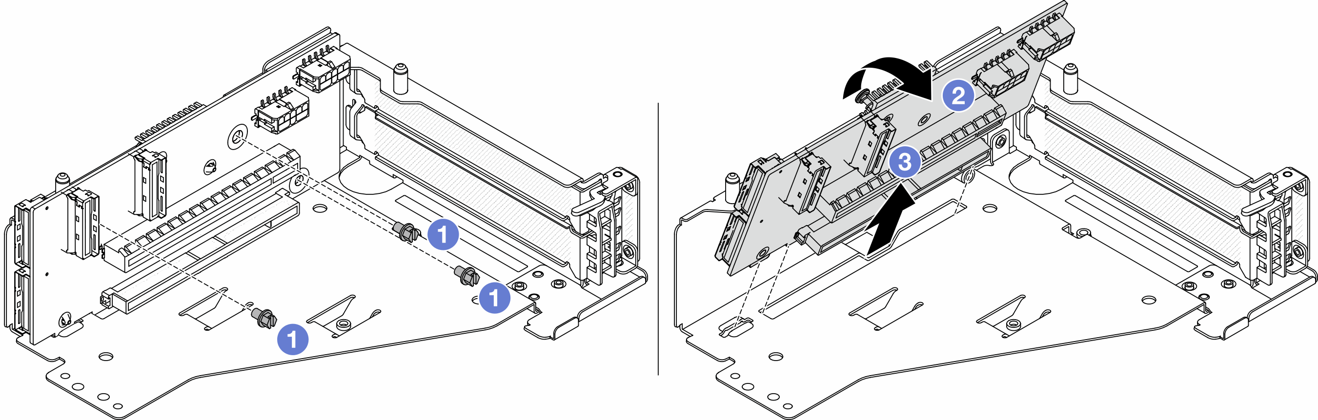
- Remove the screws that secure the riser card.
- Rotate the riser card from the top to disengage it from the screw holes on the riser cage.
- Lift the riser card out of the riser cage.
After you finish
If you are instructed to return the component or optional device, follow all packaging instructions, and use any packaging materials for shipping that are supplied to you.
Demo video