Remove the front OCP interposer card
Follow instructions in this section to remove the front OCP interposer card.
About this task
Read Installation Guidelines and Safety inspection checklist to ensure that you work safely.
Power off the server and peripheral devices and disconnect the power cords and all external cables. See Power off the server.
Prevent exposure to static electricity, which might lead to system halt and loss of data, by keeping static-sensitive components in their static-protective packages until installation, and handling these devices with an electrostatic-discharge wrist strap or other grounding system.
Procedure
- Remove the front adapter assembly.NoteThe number of cables varies according to the configuration.Figure 1. Removing the front adapter assembly
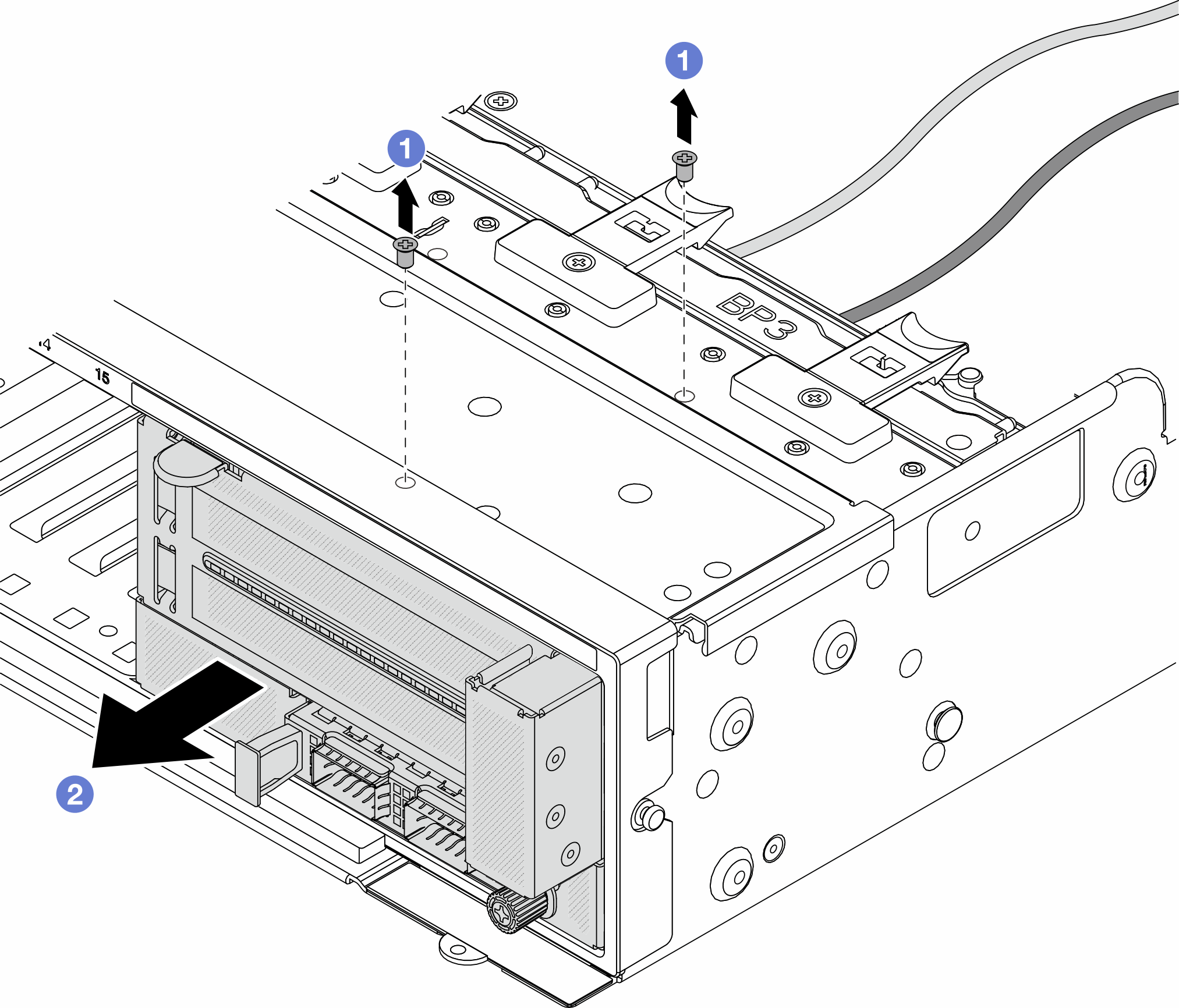
 Remove the screws that secure the assembly.
 Slide the assembly out of the front chassis.
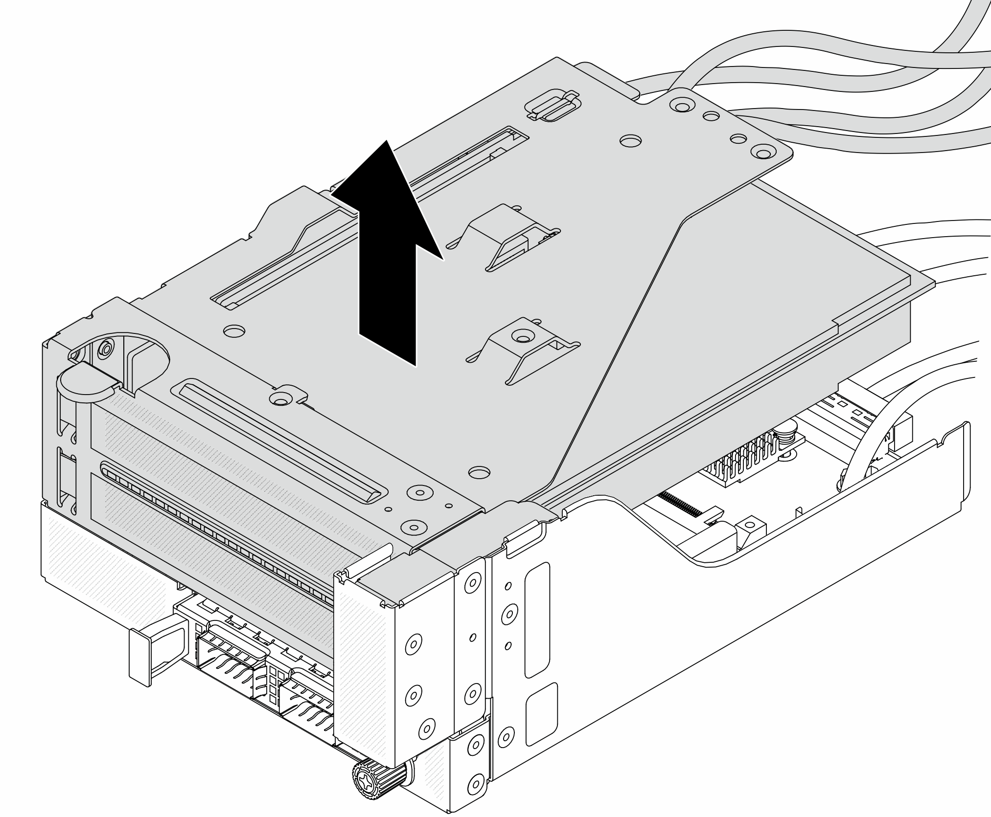
- Lift the riser 5 assembly up off the front OCP assembly, and disconnect cables from the front OCP interposer card.Figure 2. Lifting the riser 5 assembly
- Remove the OCP module from the front OCP cage.Figure 3. Removing the OCP module
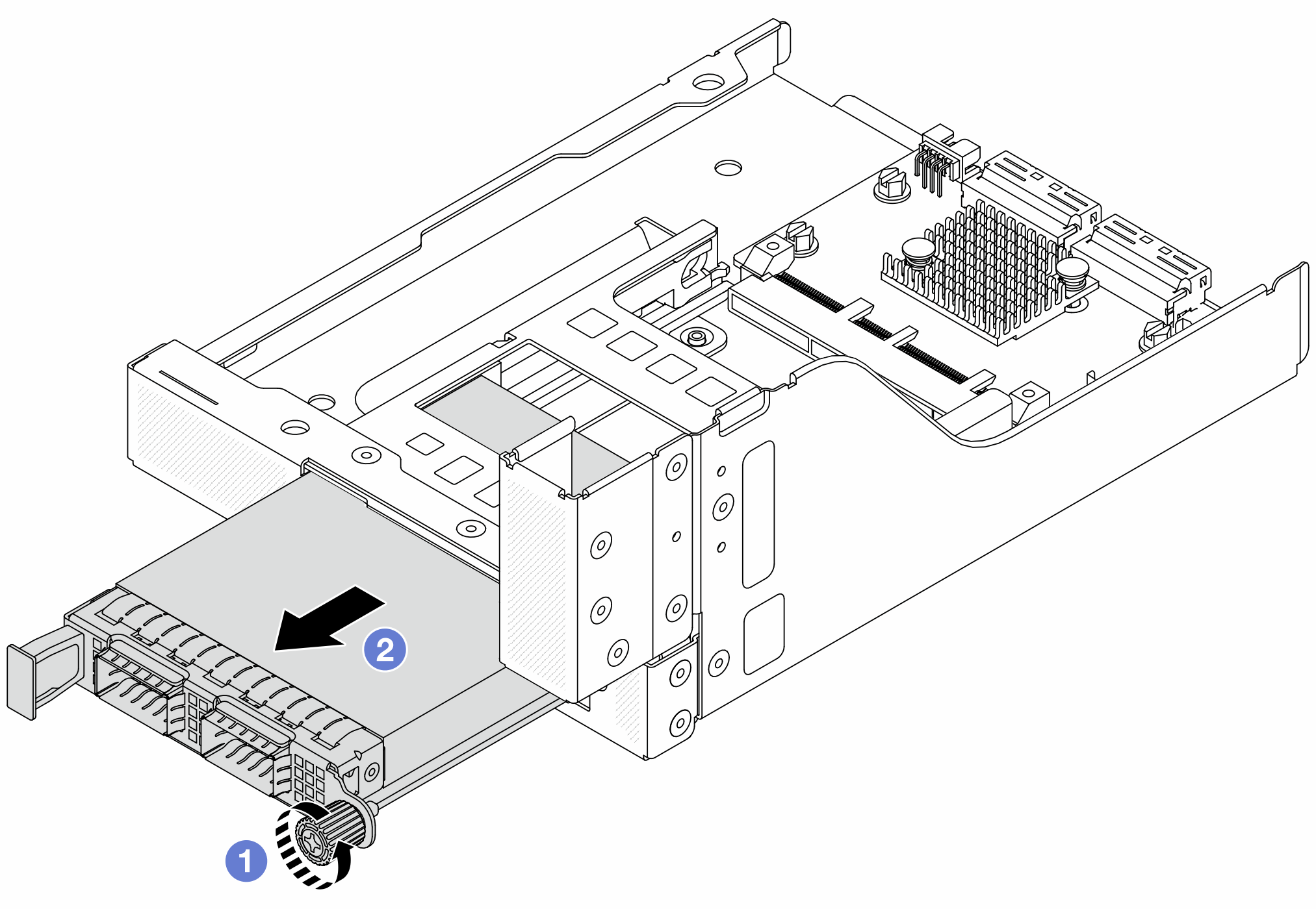
- Loosen the thumbscrew that secures the OCP module.
- Pull out the OCP module.
- Remove the front OCP interposer card.Figure 4. Removing the front OCP interposer card
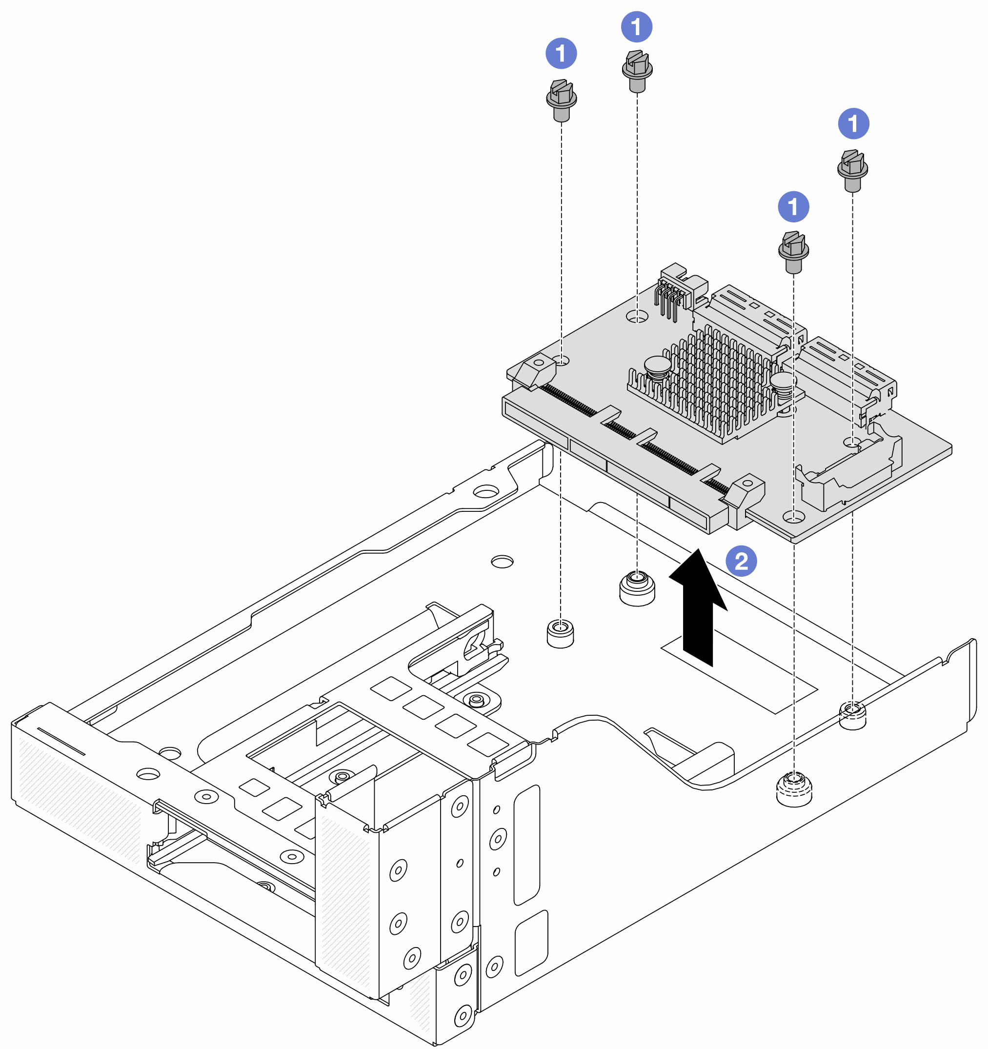
- Loosen the screws that secure the front OCP interposer card.
- Lift the front OCP interposer card up off the front OCP cage.
After you finish
Install a new front OCP interposer card. See Install the front OCP interposer card.
If you are instructed to return the component or optional device, follow all packaging instructions, and use any packaging materials for shipping that are supplied to you.
Demo video