Remove the Lenovo Neptune Processor Direct Water Cooling Module
Follow the instructions in this section to remove the Direct Water Cooling Module (DWCM).
This task must be operated by trained technicians that are certified by Lenovo Service. Do not attempt to remove or install the part without proper training and qualification.
About this task

Read Installation Guidelines and Safety inspection checklist to ensure that you work safely.
Power off the server and peripheral devices and disconnect the power cords and all external cables. See Power off the server.
Prevent exposure to static electricity, which might lead to system halt and loss of data, by keeping static-sensitive components in their static-protective packages until installation, and handling these devices with an electrostatic-discharge wrist strap or other grounding system.
| Torque screwdriver type list | Screw Type |
|---|---|
| Torx T20 head screwdriver | Torx T20 screw |
Procedure
- Remove the riser cage.
1FH riser cage
Figure 1. Removing the 1FH riser cage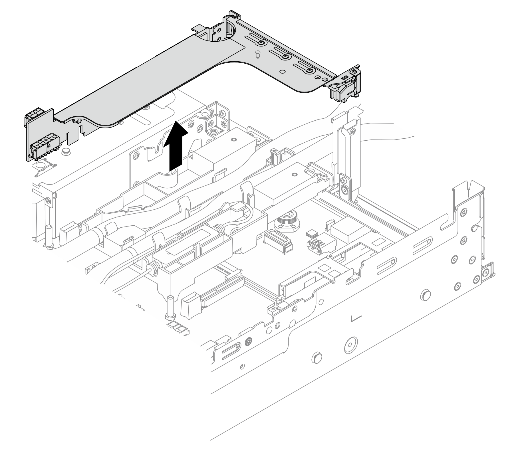
3FH riser cage
Figure 2. Removing the 3FH riser cage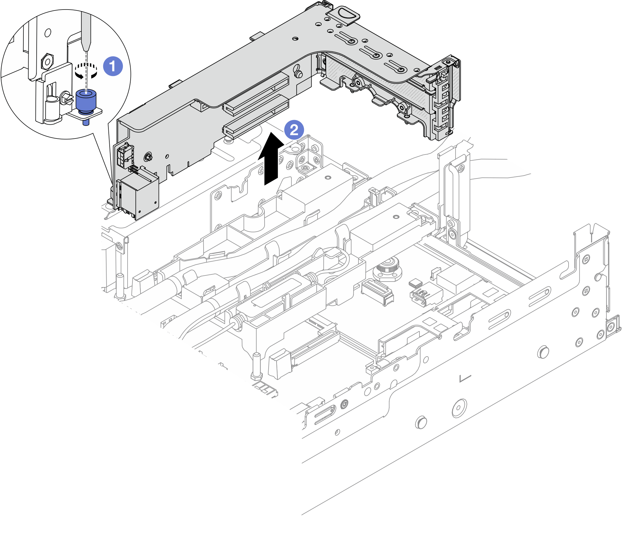
 Loosen the screw that secures the riser cage.
 Grasp the riser cage by its edges and carefully lift it straight up and off the chassis.
- Disengage the hoses and liquid detection sensor module.Figure 3. Disengaging the hoses and module
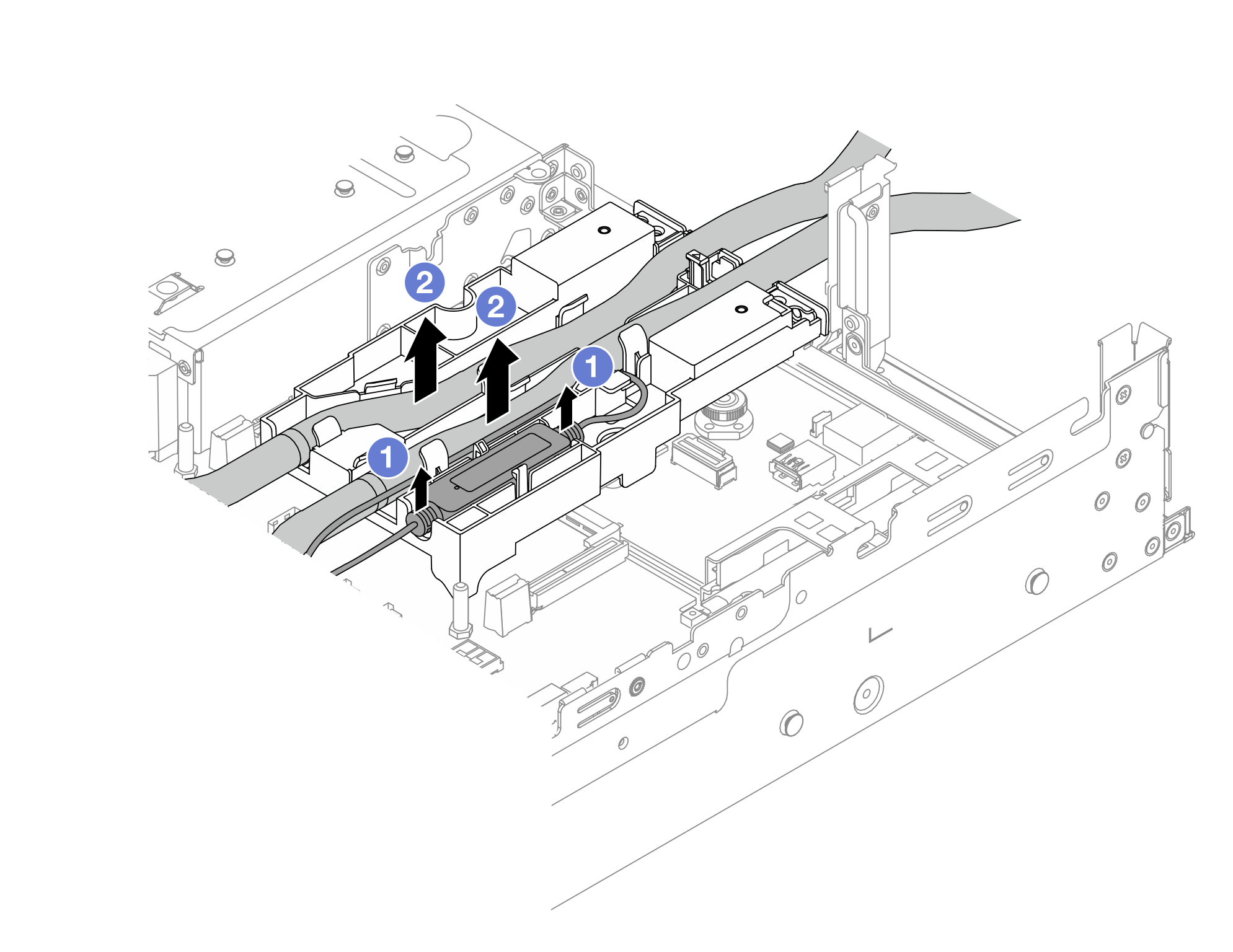
- Lift the liquid detection sensor module up from the hose holder.
- Disengage the hoses from the hose holder.
- Remove the DWCM from the processor board.Figure 4. Removing the DWCM
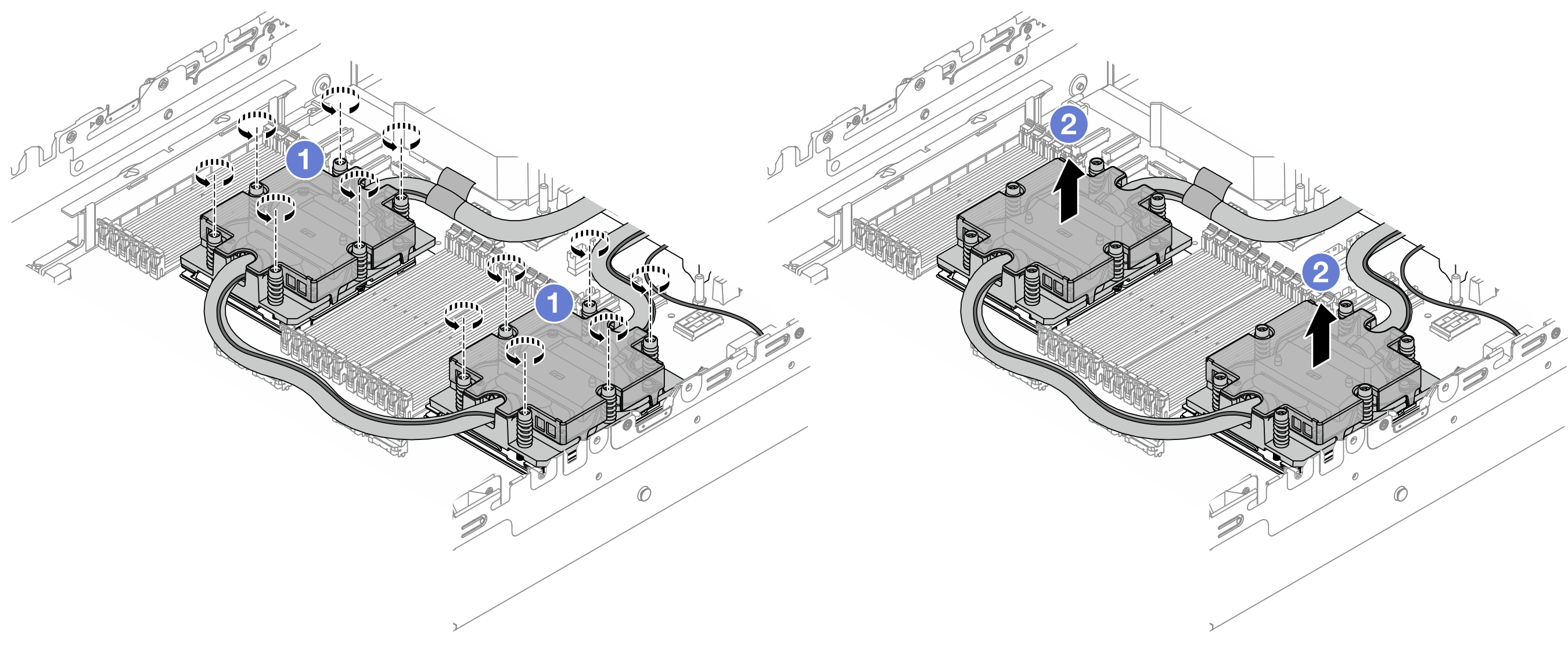
- Fully loosen all the screws in the removal sequence shown on the cold plate assembly.
- Carefully lift the DWCM from the processor socket.
- Remove the hose holder.Figure 5. Removing the hose holder
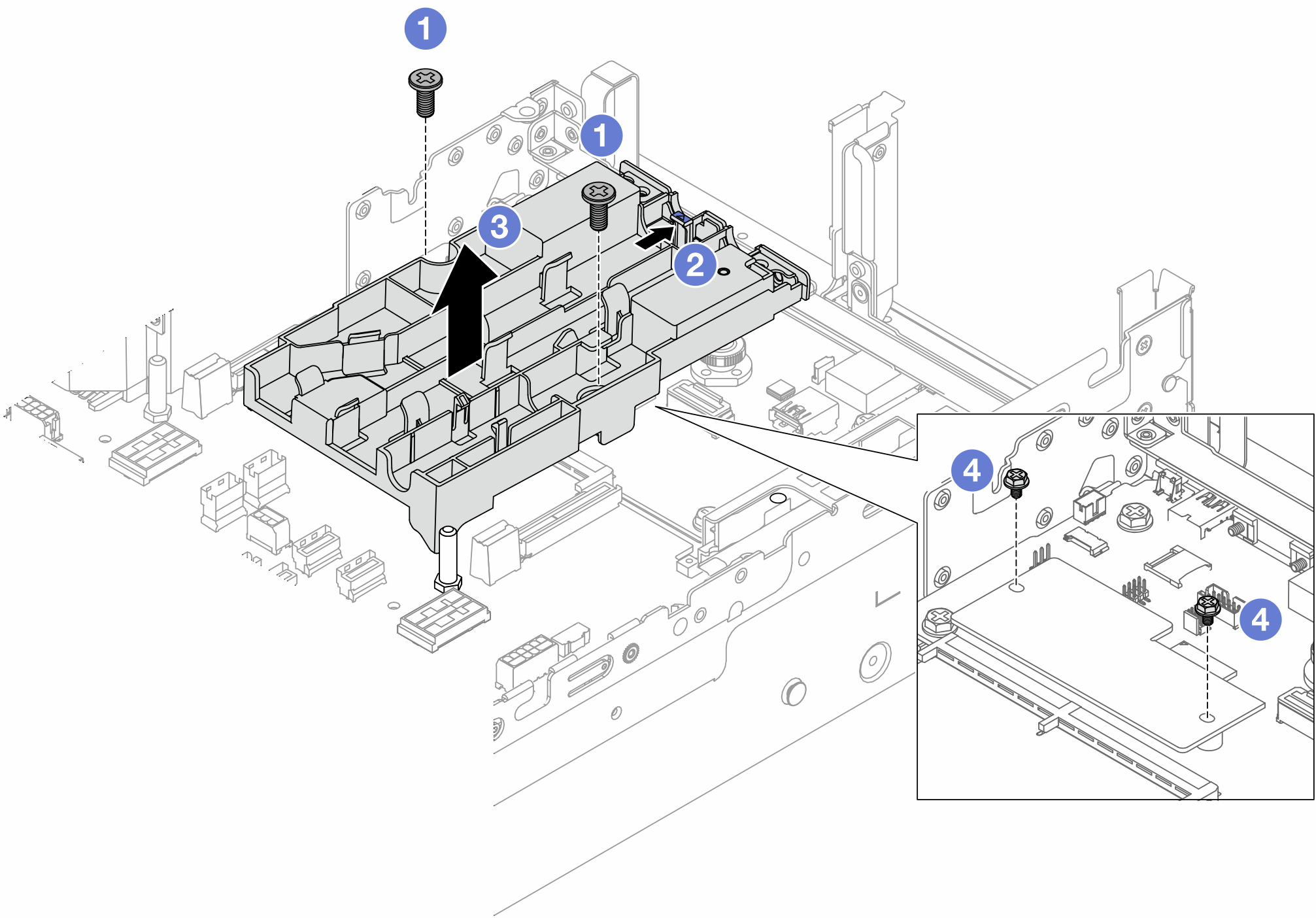
- Loosen the screws that locks the holder to the system I/O board.
- Move the blue latch towards the rear of the server.
 Lift the hose holder out of the chassis.
 Install the screws to secure the firmware and RoT security module if needed.
If you are instructed to return the component or optional device, follow all packaging instructions, and use any packaging materials for shipping that are supplied to you.
Demo video