Install the front 2.5-inch-drive backplane
Use this information to install the front 2.5-inch-drive backplane.
About this task
One backplane
Always install the backplane to drive bays 0–7.
Two backplanes
Two SATA/SAS 8-bay backplanes: install the two backplanes to drive bays 0–7 and drive bays 8–15
Two Anybay 8-bay backplanes: install the Anybay 8-bay backplane that supports SATA/SAS/NVMe drives to drive bays 0–7; install the Anybay backplane that supports pure NVMe drives to drive bays 8–15
One SATA/SAS 8-bay backplane and one Anybay 8-bay backplane: install the SATA/SAS backplane to drive bays 0–7; install the Anybay backplane to drive bays 8–15
Three backplanes
Three SATA/SAS 8-bay backplanes or Anybay backplanes that support pure NVMe drives: install the three backplanes to drive bays 0–7, drive bays 8–15, and drive bays 16–23
One SATA/SAS 8-bay backplane and two Anybay 8-bay backplanes that support pure NVMe drives: install the SATA/SAS 8-bay backplane to drive bays 0–7; install the Anybay 8-bay backplanes to drive bays 8–15 and drive bays 16–23.
One Anybay 8-bay backplane and two SATA/SAS 8-bay backplanes: install the SATA/SAS 8-bay backplanes to drive bays 0–7, drive bays 8–15; install the Anybay 8-bay backplane to drive bays 16–23.
Read Installation Guidelines to ensure that you work safely.
Prevent exposure to static electricity, which might lead to system halt and loss of data, by keeping static-sensitive components in their static-protective packages until installation, and handling these devices with an electrostatic-discharge wrist strap or other grounding system.
Procedure
- Install the 2.5-inch-drive front backplane.Figure 1. 2.5-inch-drive backplane installation
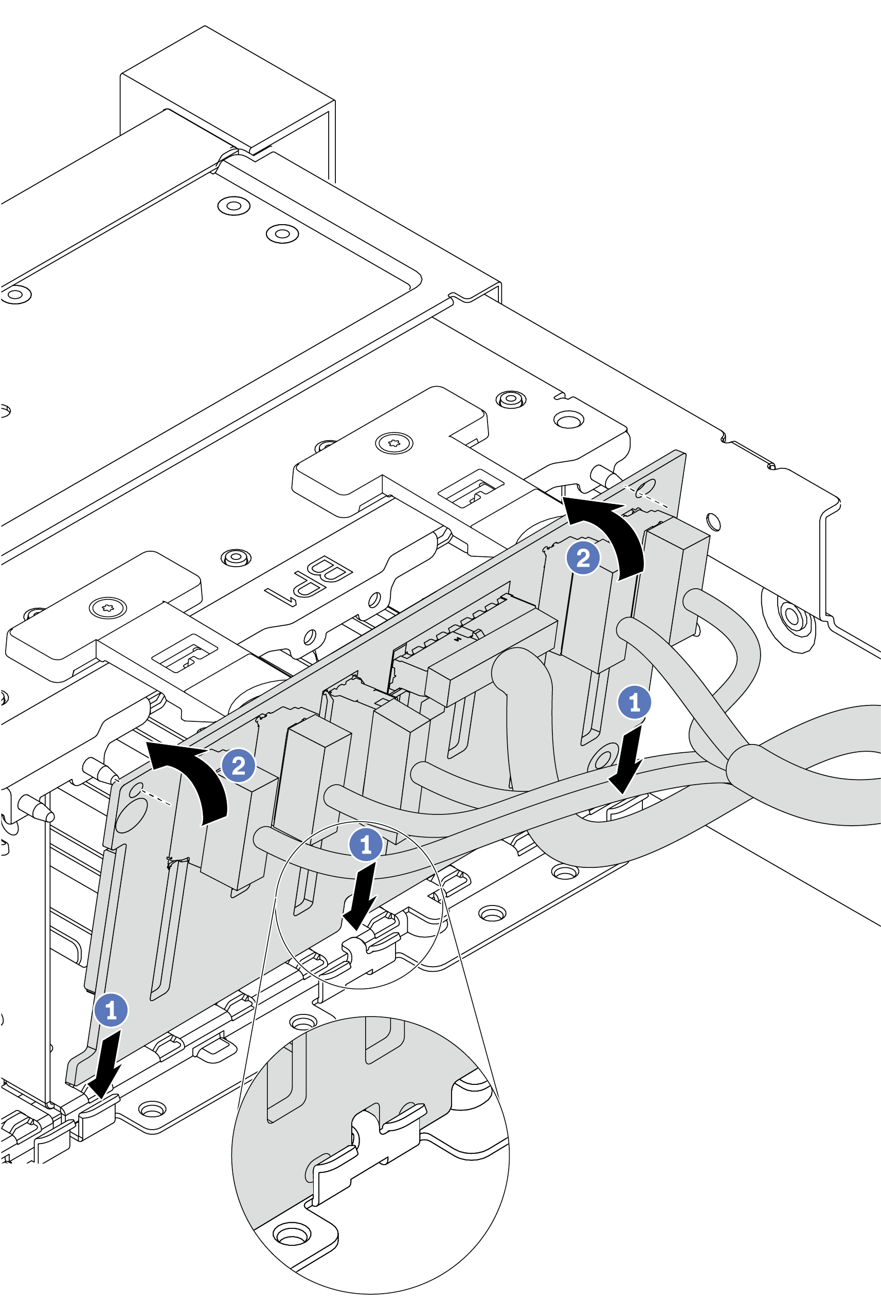
- Align the bottom of the backplane in the slots on the bottom of the chassis.
- Rotate the backplane to the vertical position and align the holes in the backplane with the pins on the chassis and press the backplane into position. The release tabs will secure the backplane in place.
After you finish
Reinstall all the drives and fillers (if any) into the drive bays. See Install a hot-swap drive.
Use the Lenovo XClarity Provisioning Manager to configure the RAID if necessary. For more information, see the
RAID Setup
section in the LXPM documentation compatible with your server at Lenovo XClarity Provisioning Manager portal page.If you have installed an Anybay backplane with U.3 NVMe drives for Trimode, enable U.3 x1 mode for the selected drive slots on the backplane through the XCC Web GUI.
Log into the XCC Web GUI, and choose from the navigation tree on the left.
In the window that is displayed, click the icon
 next to Backplane.
In the dialog box that is displayed, select the target drive slots and click Apply.
Do a DC power cycle to make the setting take effect.
Demo video