Remove the Lenovo Neptune liquid-to-air (L2A) hybrid cooling module
Follow instructions in this section to remove the Lenovo Neptune liquid-to-air (L2A) hybrid cooling module. The procedure must be executed by a trained technician.
About this task
Attention
- Read Installation Guidelines and Safety inspection checklist to ensure that you work safely.
- Power off the server and peripheral devices and disconnect the power cords and all external cables. See Power off the server.
- If the server is installed in a rack, slide the server out on its rack slide rails to gain access to the top cover, or remove the server from the rack. See Remove the server from rack.
- Update the GPU firmware whenever an SXM Over-Temperature Critical message appears in the system event log and the GPU vBIOS is downlevel. See SXM THERM OT (Thermal Over Temperature) reported in Nvidia GPU HGX SXM5 configuration (trained technicians only).
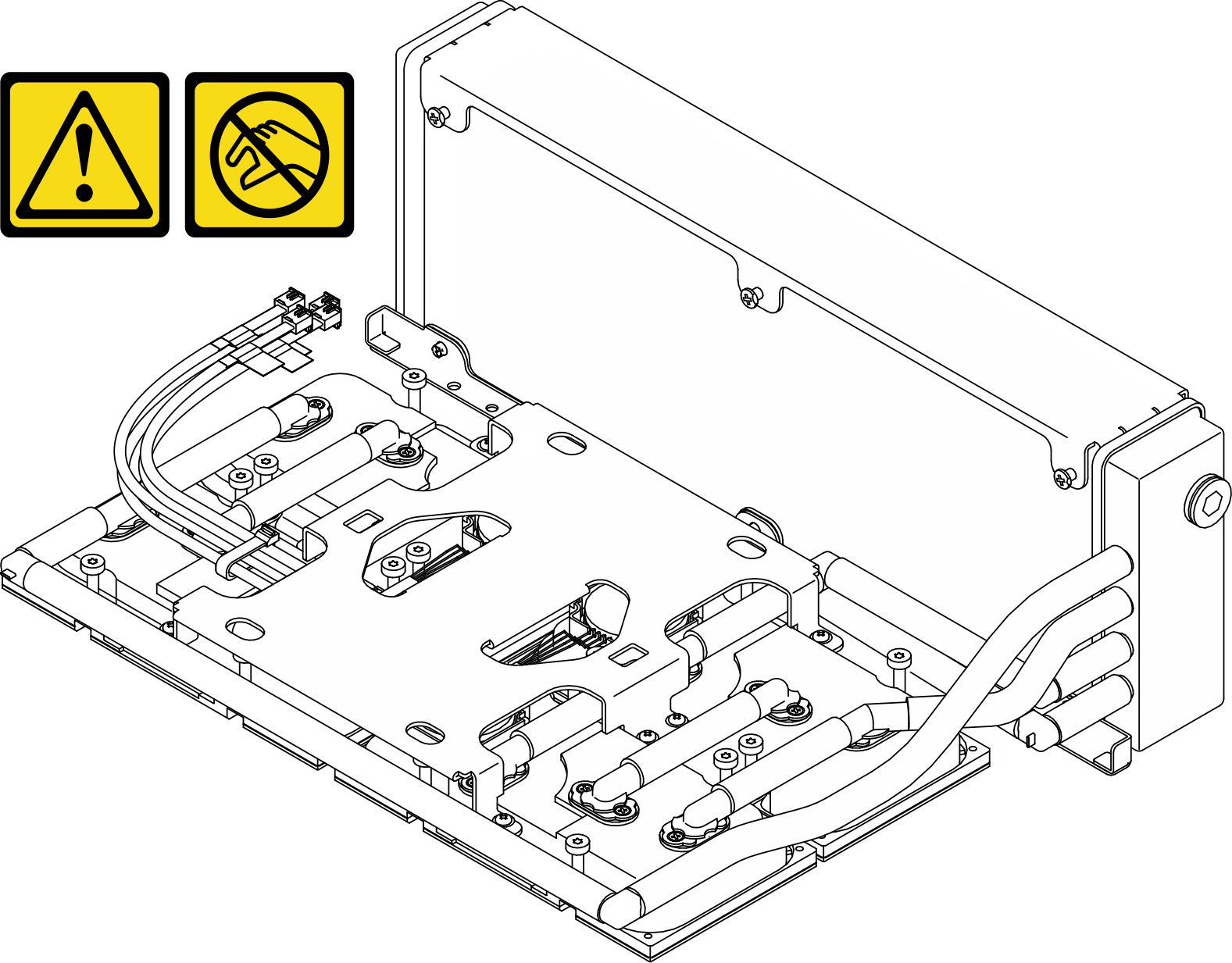
CAUTION
Do not touch the radiator fins. Touching the radiator fins might damage the L2A.
Note
Make sure you have the required tools listed below available to properly replace the component:
- Phillips #1 bit
- Torx T15 bit
- Manual torque screwdriver
- DIMM tool
- Alcohol cleaning pad
- SXM5 PCM Kit
- SR675 V3 water loop putty pad kit
- SR675 V3 water loop service kit
Important
Putty pad/phase change material (PCM) replacement guidelines
- Before replacing the putty pad/PCM, gently clean the hardware surface with an alcohol cleaning pad.
- Hold the putty pad/PCM carefully to avoid deformation. Make sure no screw hole or opening is blocked by the putty pad/PCM.
- Do not use expired putty pad/PCM. Check the expiry date on putty pad/PCM package. If the putty pads/PCM are expired, acquire new ones to properly replace them.
Procedure
- Make preparation for this task.
- Unfasten the two cable ties on the front drive tray to release the cables.Figure 1. Unfastening the cable ties
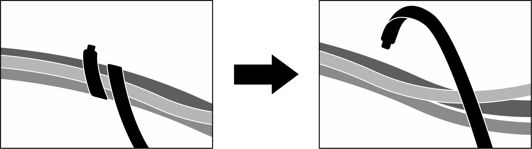
- Unfasten the two cable ties on the front drive tray to release the cables.
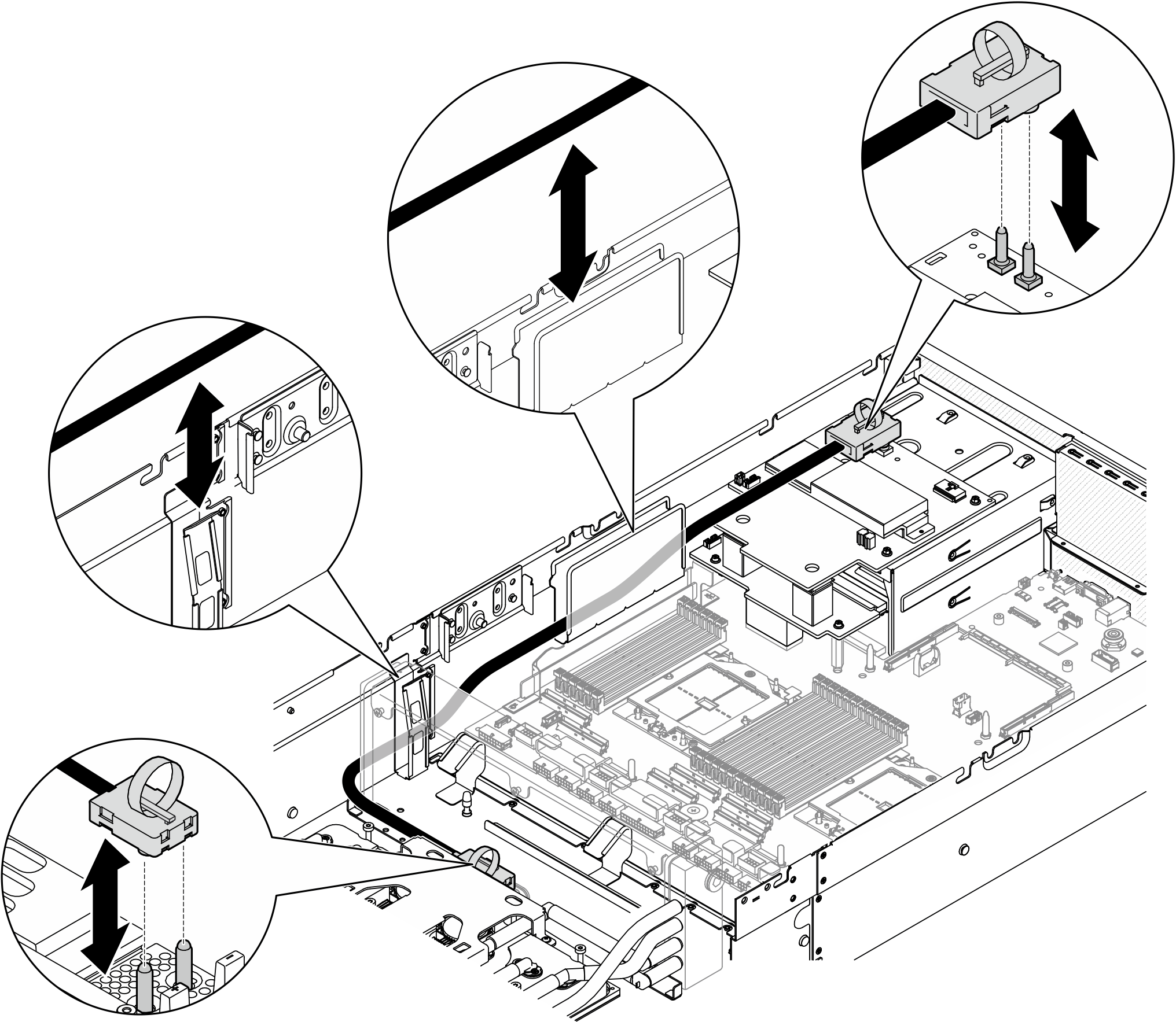
- Hold the strap on the SXM5 GPU board assembly power cable, and disconnect it from the SXM5 GPU board assembly and the SXM5 GPU power distribution board.Figure 2. SXM5 GPU board assembly power cable disconnection
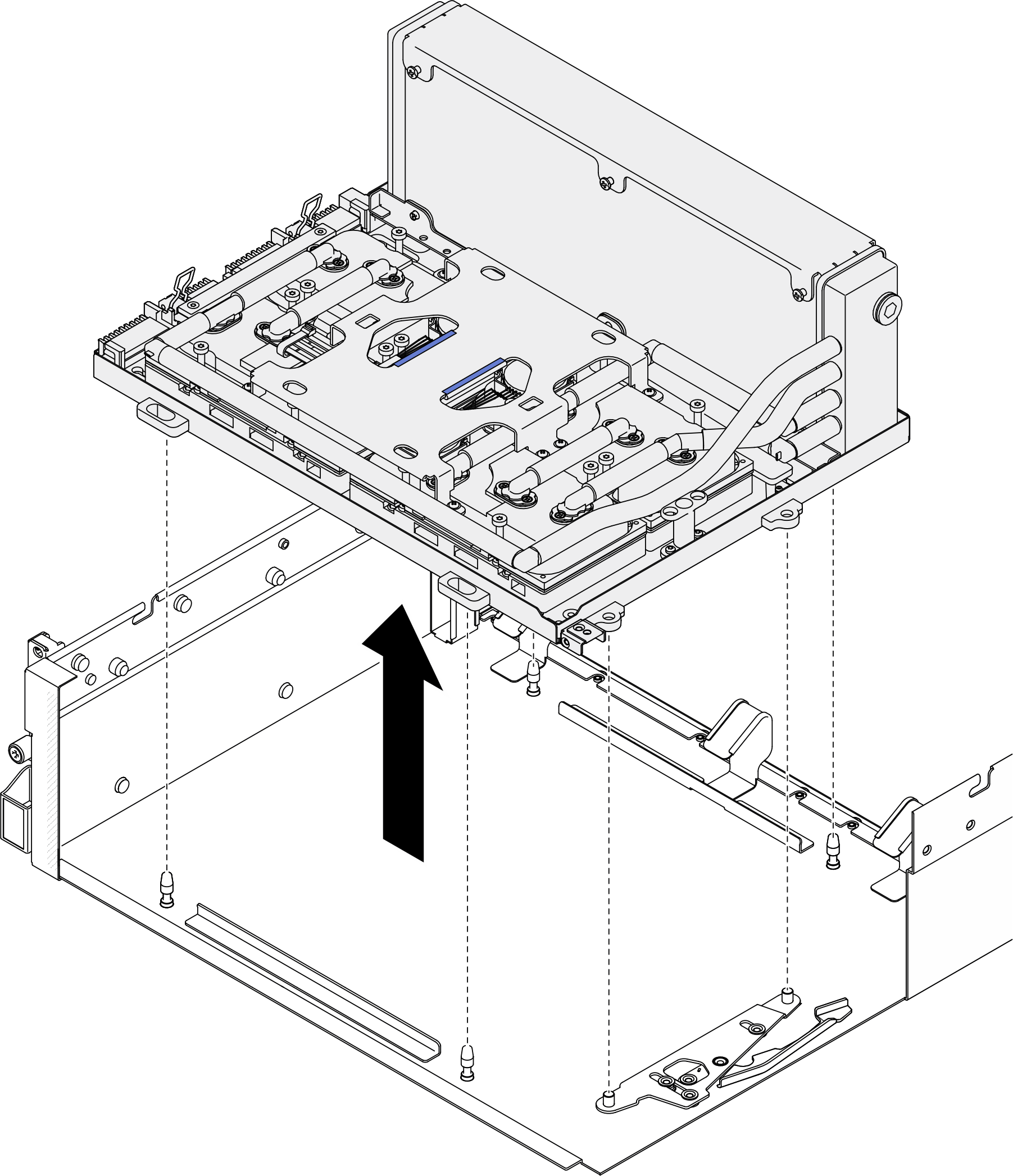
- Hold the radiator by its upper edge and hold the cold plate assembly by its lifting handle; then, lift the GPU-L2A assembly out of the chassis.Figure 3. GPU-L2A assembly removal
- Remove the six Phillips #1 screws (M3 x 5 mm) that secure the radiator to the GPU tray.NoteLoosen or tighten the screws with a torque screwdriver set to the proper torque. For reference, the torque required for the screws to be fully loosen or tighten is 0.45+0 /- 0.06 newton-meter, 4.0+0/- 0.5 inch-pound.Figure 4. Phillips #1 screw removal
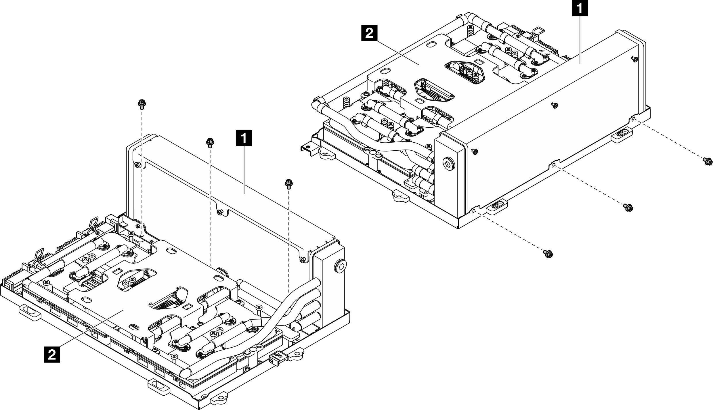
1 Radiator 2 Cold plate assembly - Remove the cold plate screws (sixteen Torx T15 screws).Important
- Make sure to use the manual torque screwdriver in this step.
- The cold plate label may differ; make sure to follow screw removal sequence specified in this step to prevent cold plate tilting.
- Loosen or tighten the screws with a torque screwdriver set to the proper torque. For reference, the torque required for the screws to be fully loosen or tighten is 0.45+0 /- 0.06 newton-meter, 4.0+0/- 0.5 inch-pound.
- Follow the screw removal sequence (screw 1 > 2 > 3 > 4), and loosen each of the four screws on the cold plate 4 by 360 degrees. Repeat to ensure all screws are fully loosened.
- Follow the screw removal sequence (screw 1 > 2 > 3 > 4), and loosen each of the four screws on the cold plate 3 by 360 degrees. Repeat to ensure all screws are fully loosened.
- Follow the screw removal sequence (screw 1 > 2 > 3 > 4), and loosen each of the four screws on the cold plate 2 by 360 degrees. Repeat to ensure all screws are fully loosened.
- Follow the screw removal sequence (screw 1 > 2 > 3 > 4), and loosen each of the four screws on the cold plate 1 by 360 degrees. Repeat to ensure all screws are fully loosened.
Figure 5. Torx T15 screw removal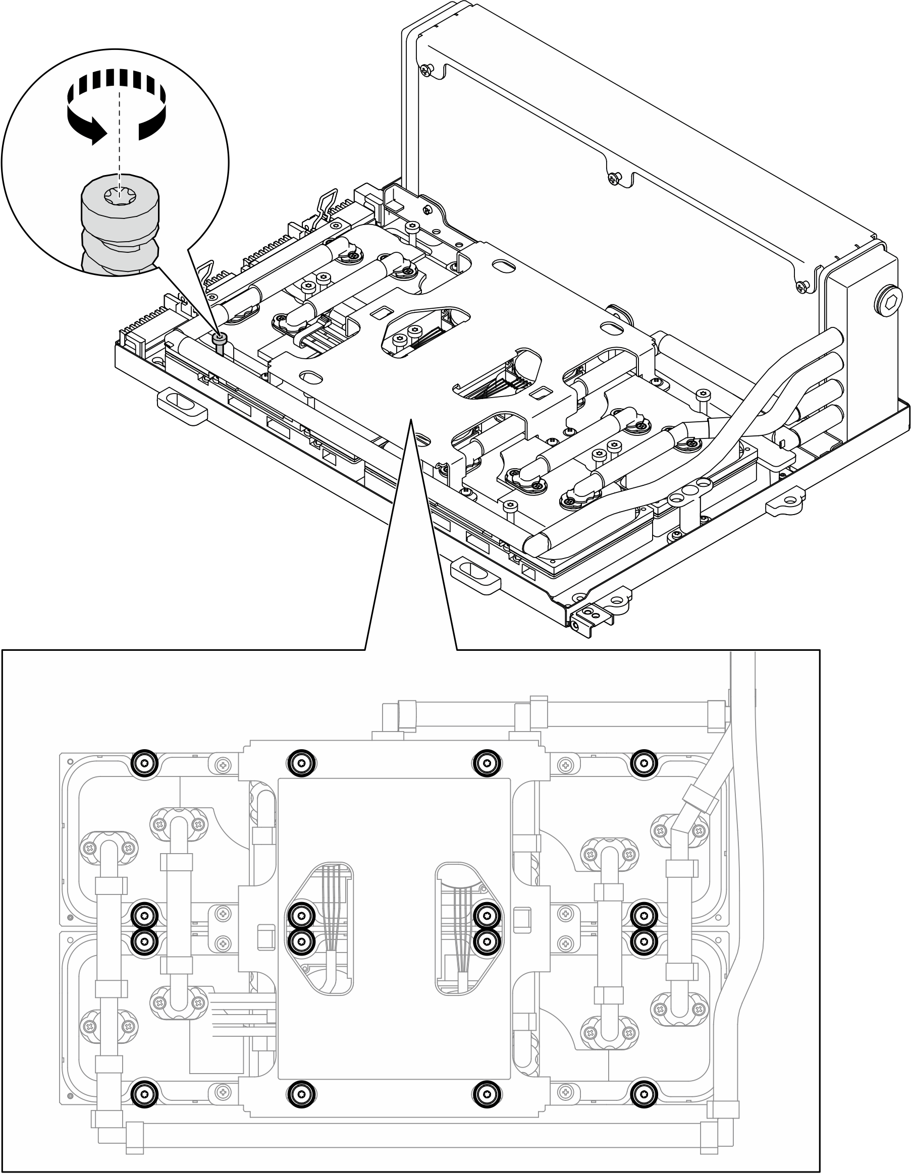
- Disengage the four cold plates from the SXM5 GPUs.
- Insert the DIMM tool into the gap between the cold plate and GPU, beneath the round hole on the cold plate, as shown in the illustration.
- Gently press down the DIMM tool to disengage the cold plate from the GPU.
- Repeat steps 6a and 6b to disengage the remaining three cold plates from the GPUs.
AttentionEnsure the DIMM tool is not inserted beyond the round hole to avoid damaging the GPUs.Figure 6. Cold plate disengagement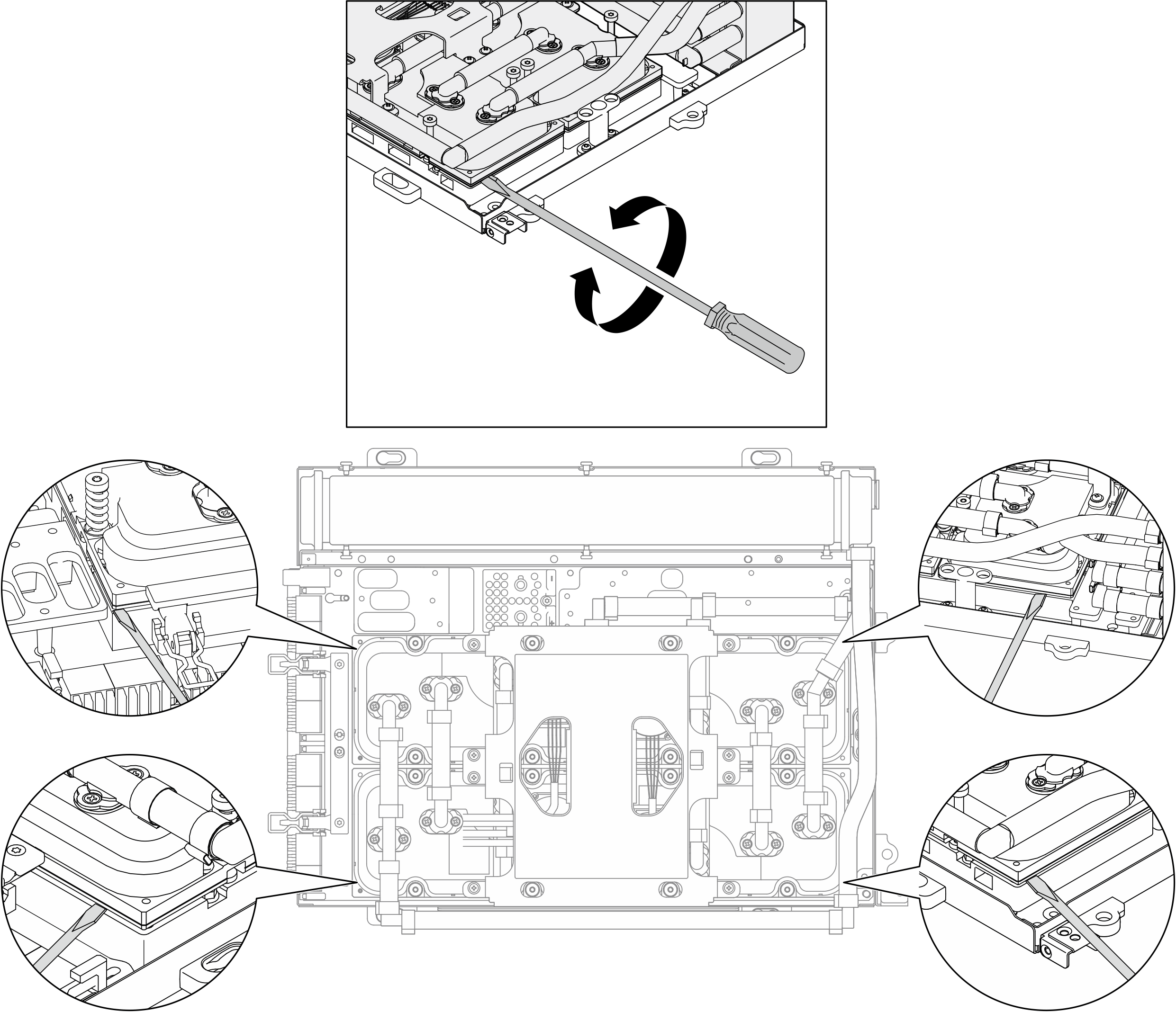
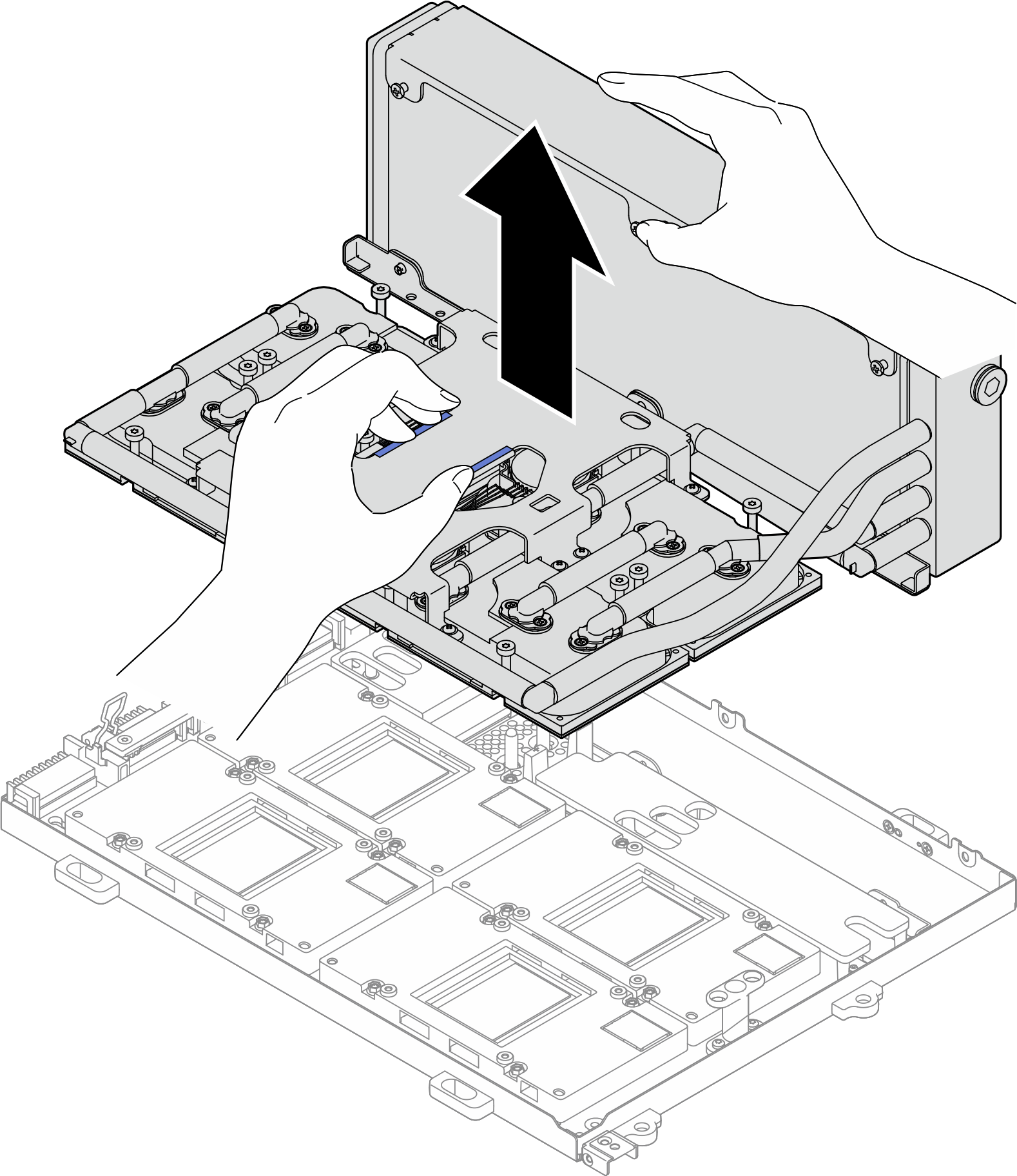
- Hold the radiator by its upper edge and hold the cold plate assembly by its lifting handle; then, lift the L2A from the SXM5 GPU board assembly.Figure 7. L2A removal
- Turn the L2A upside down.
 Hold the radiator by its upper edge and hold the cold plate assembly by its lifting handle; then, put the L2A into the shipping box.
 Place the top cover of the shipping box on top of the L2A and ensure it is firmly seated.
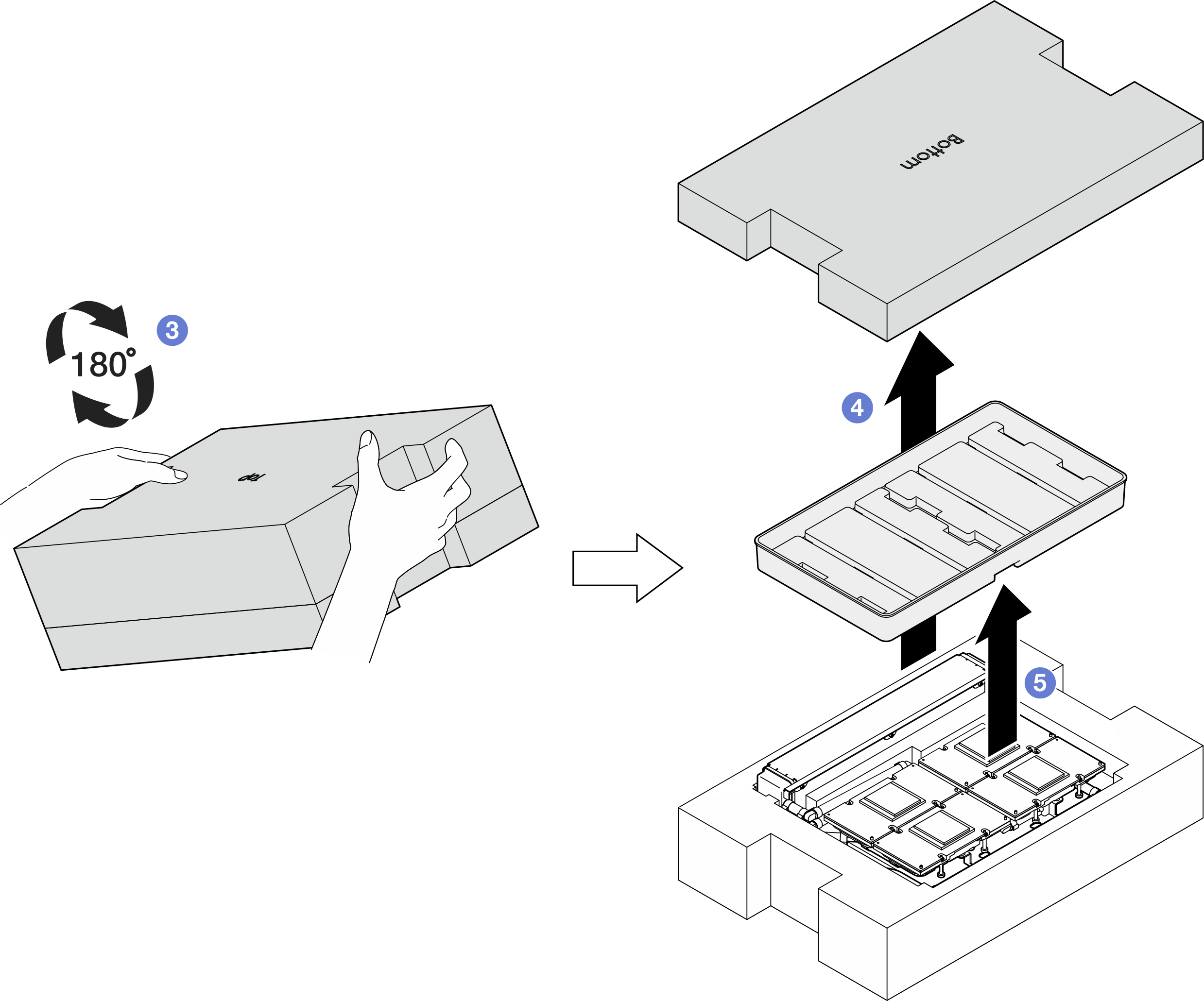
 Hold the shipping box and carefully turn it upside down.
 Remove the bottom cover of the shipping box.
 Remove the plastic tray and the bottom of the cold plate assembly is facing up.Figure 8. Turning the L2A upside down
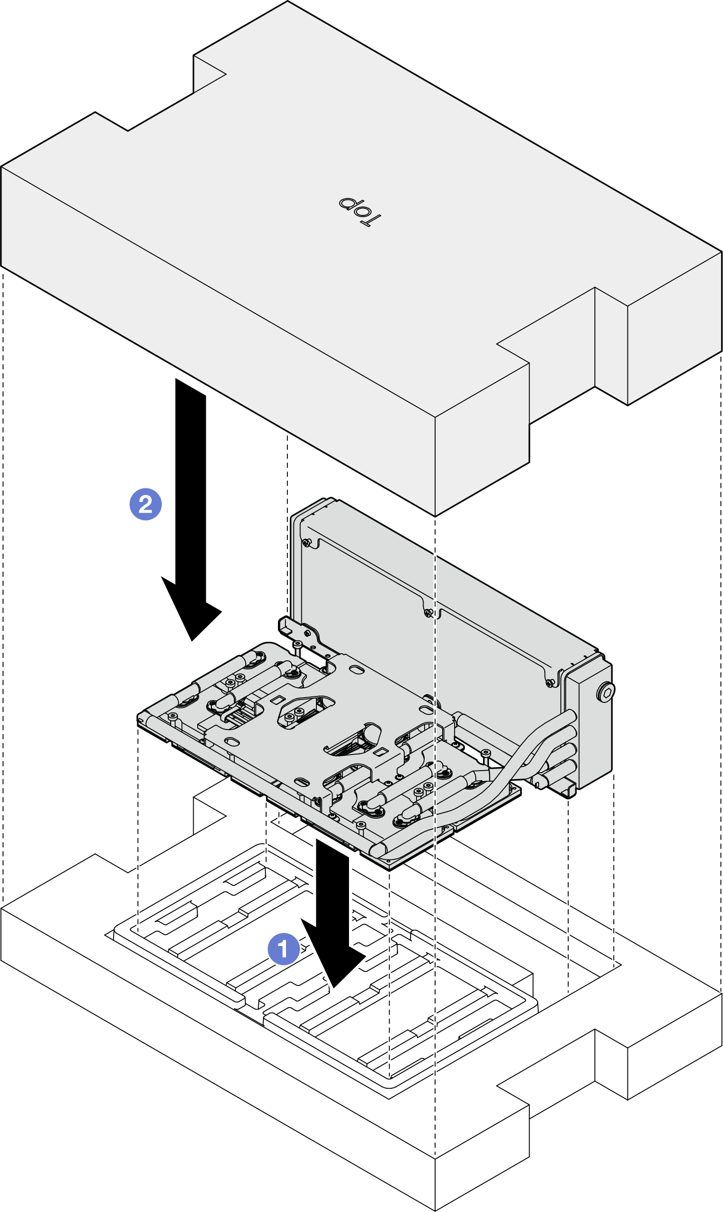
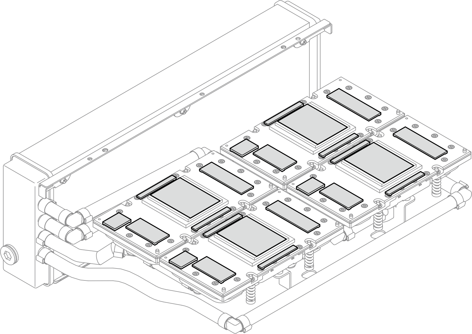
- Wipe any remaining PCM and putty pads off from all the cold plates with alcohol cleaning pads.Figure 9. Wiping PCM and putty pads off from the cold plates
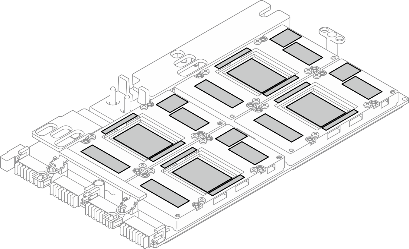
- Gently wipe any remaining PCM and putty pads off from all the SXM5 GPUs with alcohol cleaning pads to avoid SXM5 GPU damages.AttentionThe electrical components around the die on the SXM5 GPUs are extremely delicate. When cleaning the SXM5 GPU die, avoid touching the electrical components to prevent damages.Figure 10. Wiping PCM and putty pads off from the SXM5 GPUs
After you finish
- To replace the SXM5 GPU board, see SXM5 GPU board assembly replacement (trained technician only).
- If you are instructed to return the component or optional device, follow all packaging instructions, and use any packaging materials for shipping that are supplied to you.
Demo video
Give documentation feedback