Install the drive cage
Follow instructions in this section to install the drive cage. The procedure must be executed by a trained technician.
About this task
Attention
- Read Installation Guidelines and Safety inspection checklist to ensure that you work safely.
- Touch the static-protective package that contains the component to any unpainted metal surface on the server; then, remove it from the package and place it on a static-protective surface.
Procedure
 Align the drive cage with its opening in the front of the system shuttle and push it into the shuttle.
 Locate the two screws holes marked with E on both sides of the system shuttle, and seven screws holes on the drive cage; then, fasten the nine screws to secure the drive cage.Figure 1. Drive cage installation
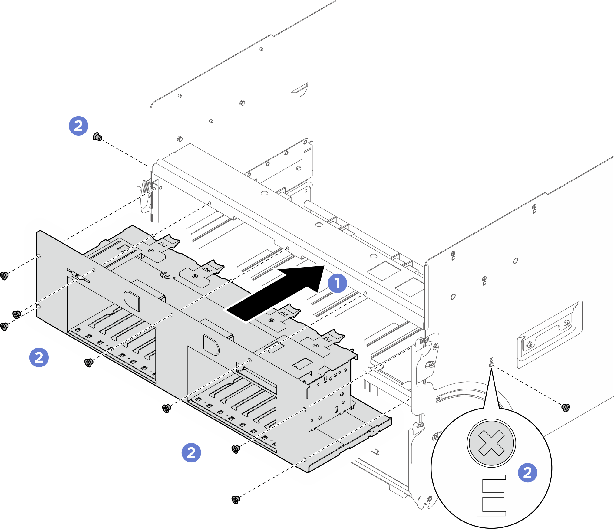
After you finish
- Reinstall all the 2.5-inch hot-swap drives or drive bay fillers (if any) into the drive bays. See Install a 2.5-inch hot-swap drive
- Reinstall the integrated diagnostics panel. See Install the integrated diagnostics panel.
- Reinstall the FIO/PCI cage. See Install the FIO/PCI cage.
- Push the system shuttle fully into the chassis.
- Lift the two lock latches on both sides of the shuttle.
- Slide the shuttle into the chassis.
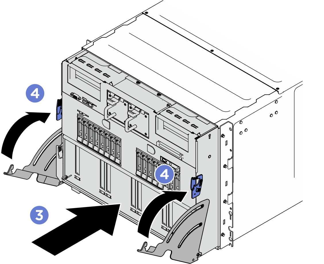
 Push the shuttle fully into the chassis.
 Rotate the two release levers until they lock into place.
Figure 2. System shuttle installation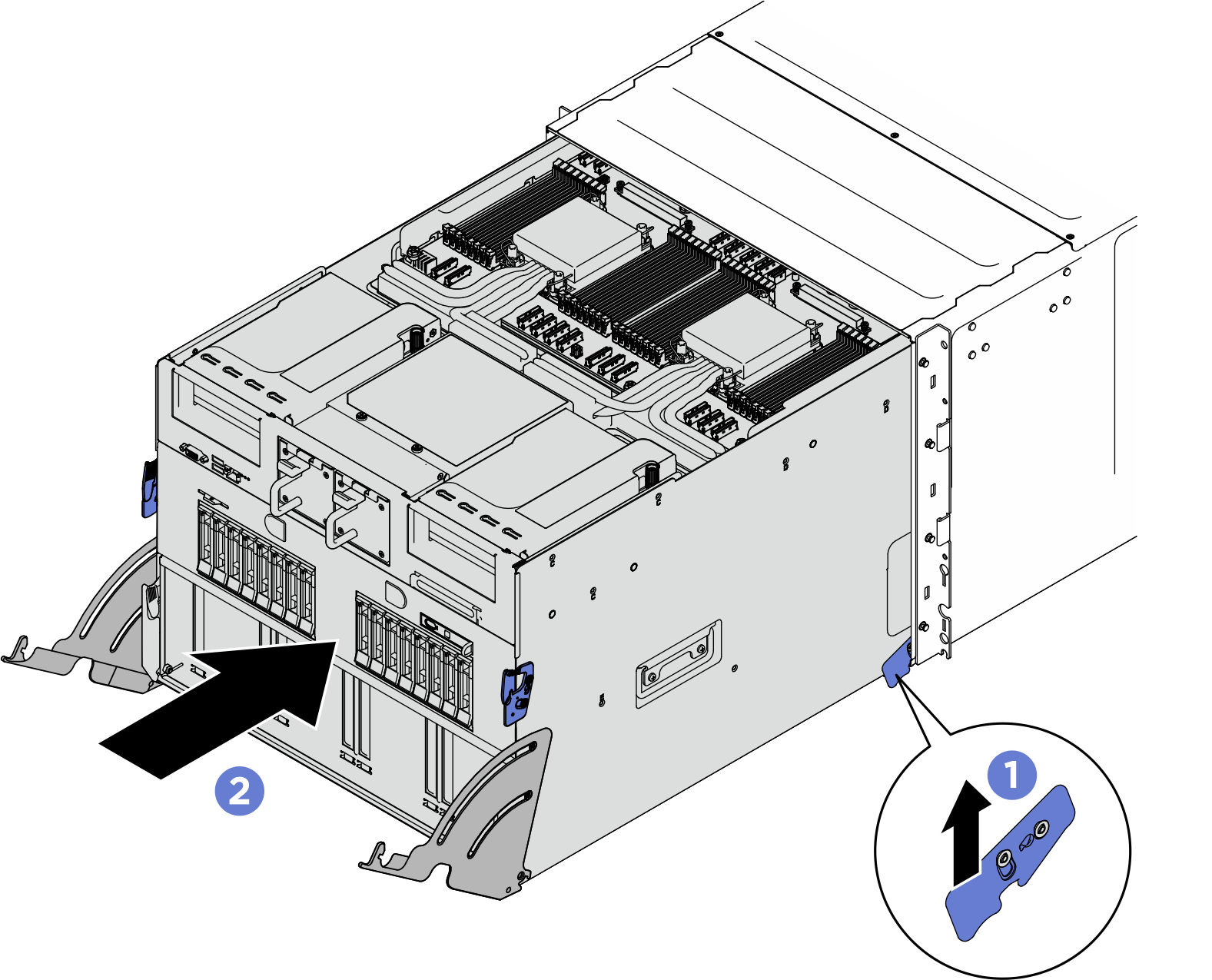
- Complete the parts replacement. See Complete the parts replacement.
Give documentation feedback