2.5-inch drive backplane cable routing
Use the section to understand the cable routing for the 2.5-inch drive backplane.
Note
- If necessary, attach the labels to both ends of the cables.
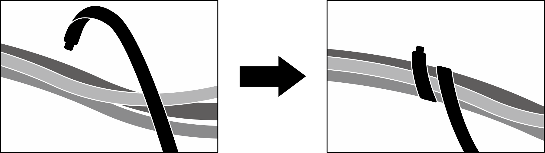
 Attach the white space portion of the label to one end of the cable.
 Wrap the label around the cable and attach it to the white space portion.
- Repeat to attach the other label to the opposite end of the cable.
Figure 1. Label application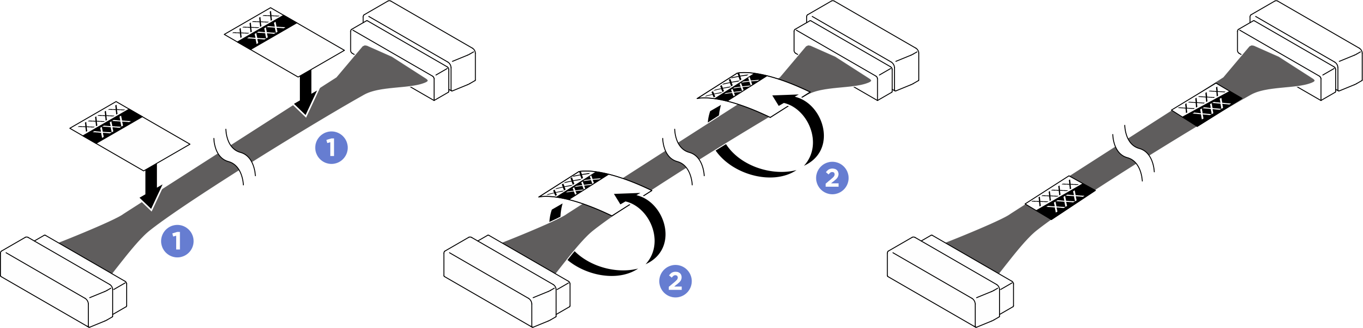
- Pass the power cables through the cable holder and baffle assembly, then route them under the compute tray as illustrated below.
Based on the location of the drive backplane, select the corresponding routing plan:
After you finish cable routing, bundle the cables with cable ties. See Bundle cables connected to the PCIe switch board (bundles 2, 3, 4, and 5).
Backplane 1
Figure 2. Backplane 1 cable routing
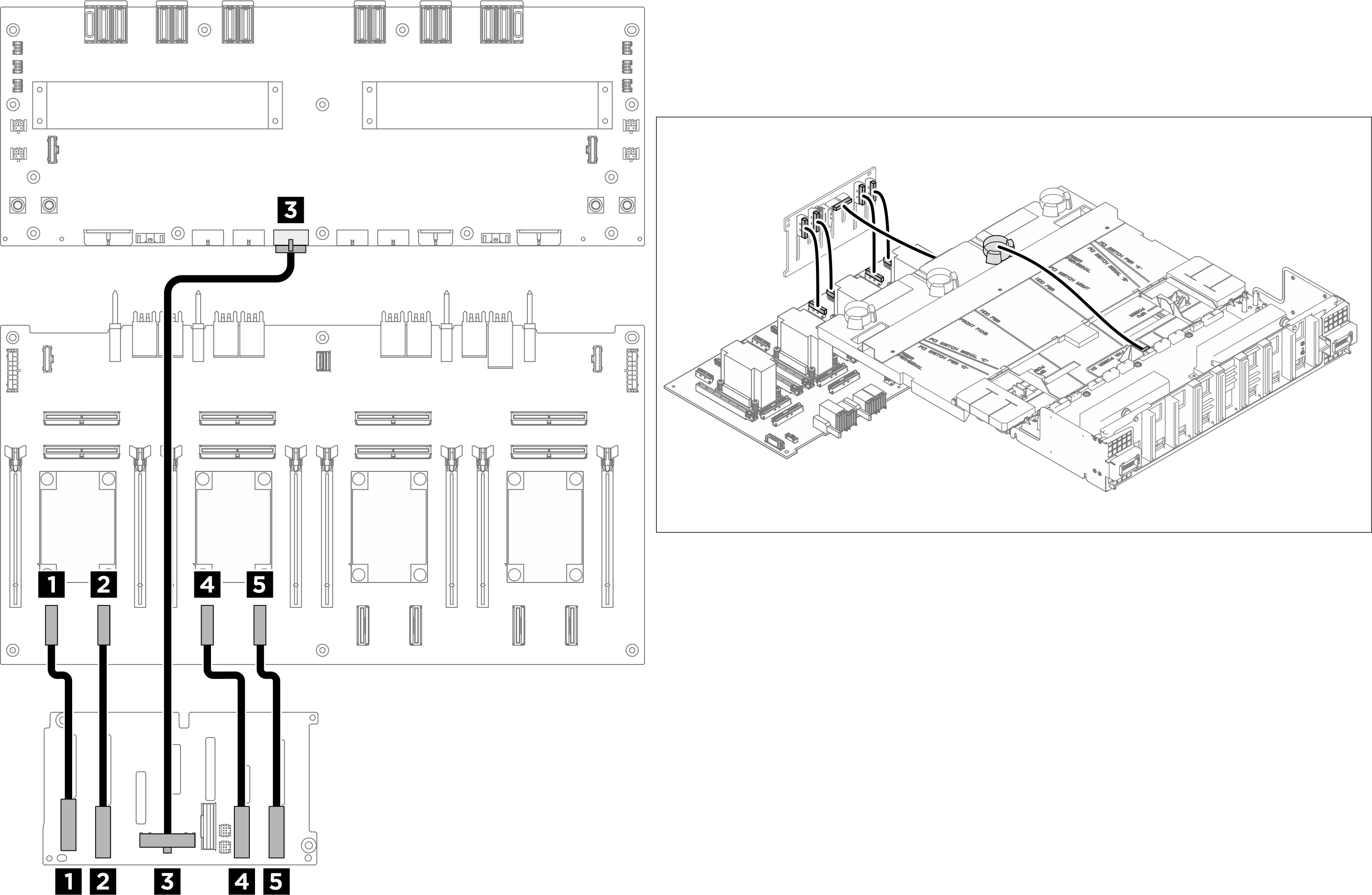
| From | To | Label |
|---|---|---|
| 1 Backplane 1: NVMe connector 0-1 | 1 PCIe switch board: NVMe connector 1 (NVME1) |
|
| 2 Backplane 1: NVMe connector 2-3 | 2 PCIe switch board: NVMe connector 2 (NVME2) |
|
| 3 Backplane 1: Power connector | 3 Power distribution board: Backplane 1 power connector (BP1 PWR) |
|
| 4 Backplane 1: NVMe connector 4-5 | 4 PCIe switch board: NVMe connector 3 (NVME3) |
|
| 5 Backplane 1: NVMe connector 6-7 | 5 PCIe switch board: NVMe connector 4 (NVME4) |
|
Backplane 2
Figure 3. Backplane 2 cable routing
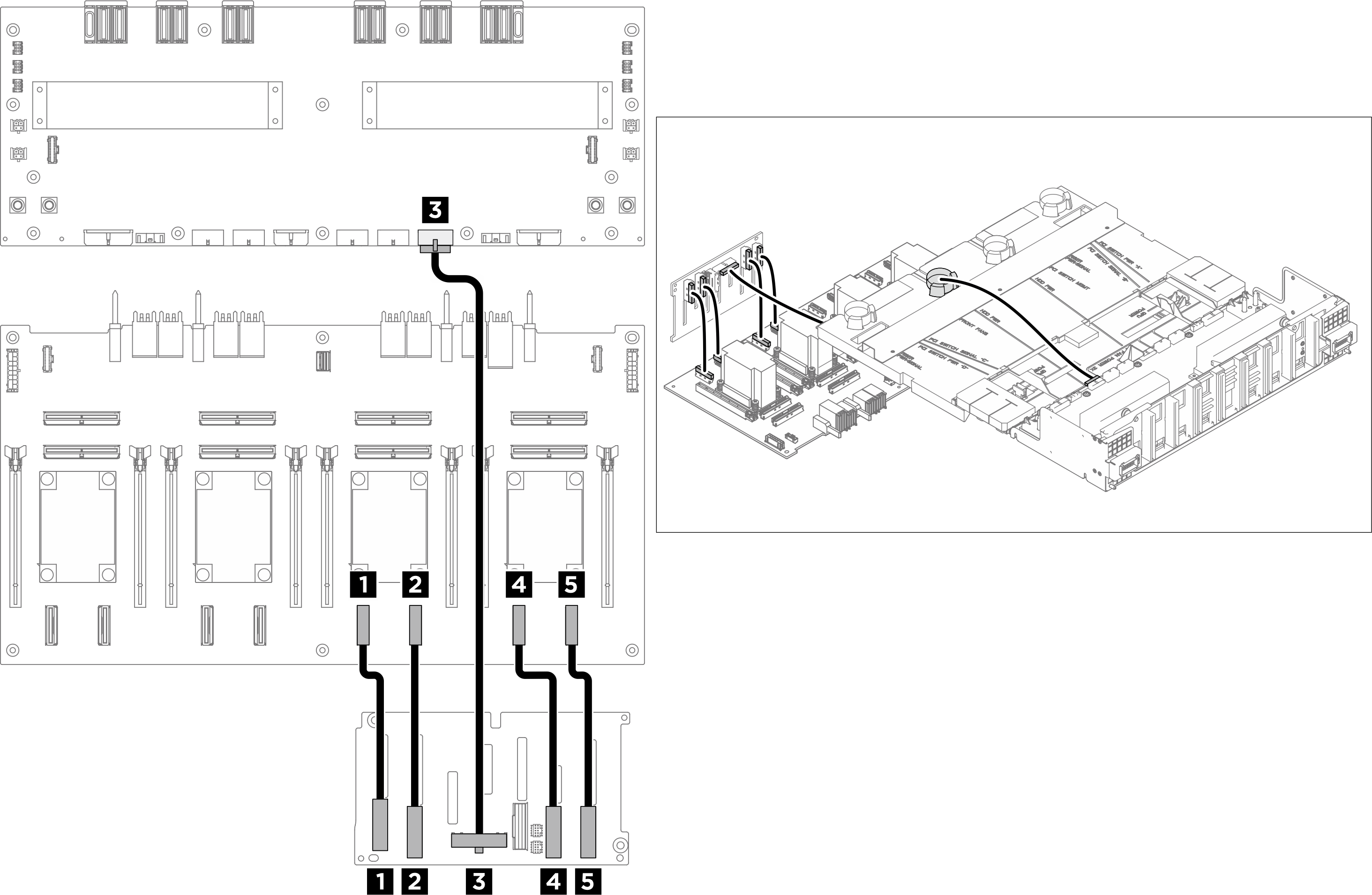
| From | To | Label |
|---|---|---|
| 1 Backplane 2: NVMe connector 0-1 | 1 PCIe switch board: NVMe connector 5 (NVME5) |
|
| 2 Backplane 2: NVMe connector 2-3 | 2 PCIe switch board: NVMe connector 6 (NVME6) |
|
| 3 Backplane 2: Power connector | 3 Power distribution board: Backplane 2 power connector (BP2 PWR) |
|
| 4 Backplane 2: NVMe connector 4-5 | 4 PCIe switch board: NVMe connector 7 (NVME7) |
|
| 5 Backplane 2: NVMe connector 6-7 | 5 PCIe switch board: NVMe connector 8 (NVME8) |
|
Bundle cables connected to the PCIe switch board
- Divide the cables connected to the PCIe switch board into six bundles, and secure them to the crossbar with cable ties.
- Keep the cables away from the PCIe switch board heat sinks.
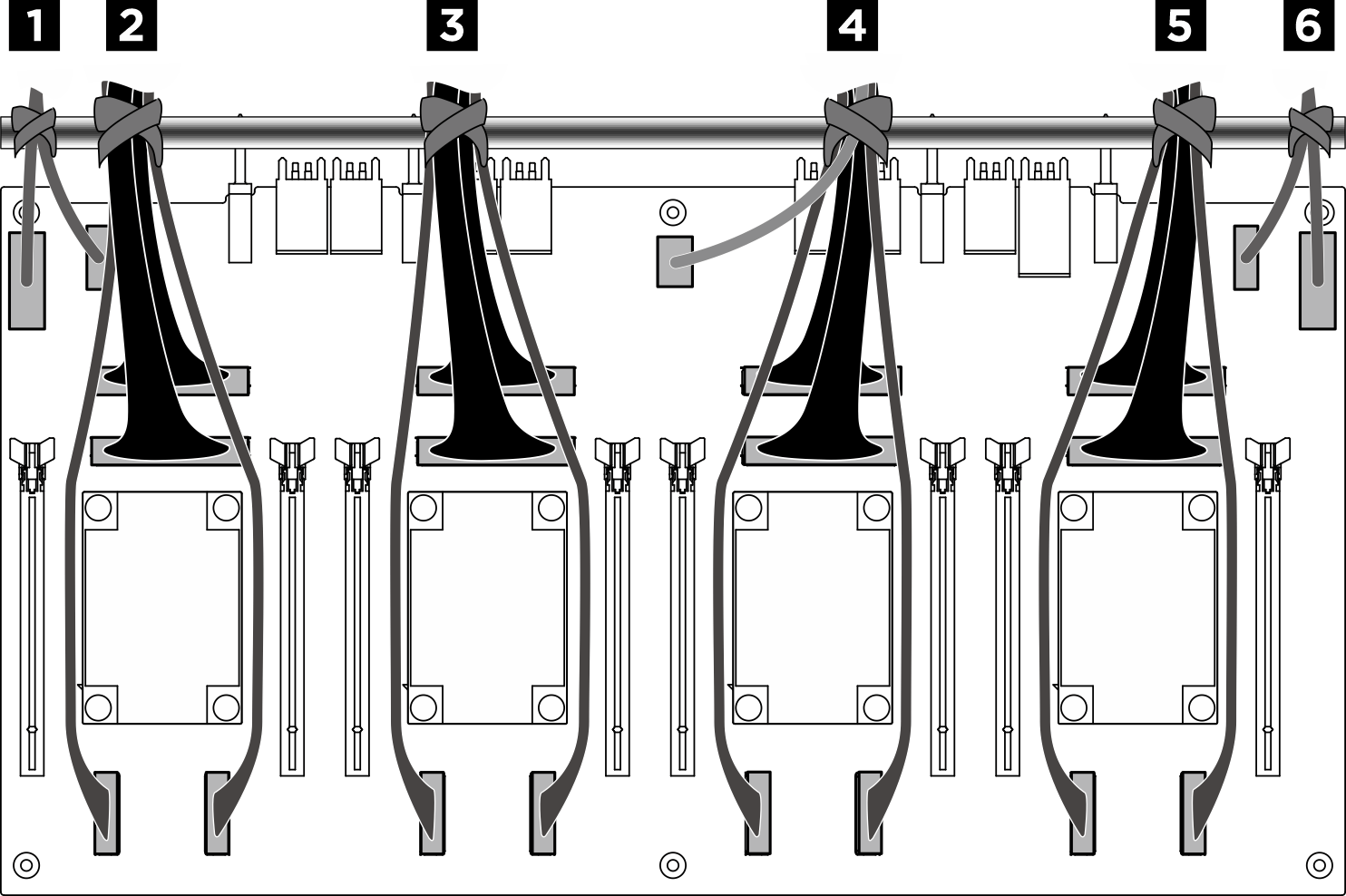
Figure 4. Securing cables with cable ties
| Bundle | Cable | Connector (on PCIe switch board) |
|---|---|---|
| 1 | Two cables:
|
|
| 2 | Four cables:
|
|
| 3 | Four cables:
|
|
| 4 | Five cables:
|
|
| 5 | Four cables:
|
|
| 6 | Two cables:
|
|
Give documentation feedback