PCIe riser cable routing
Use the section to understand the cable routing for the PCIe risers.
Note
- If necessary, attach the labels to both ends of the cables.
 Attach the white space portion of the label to one end of the cable.
 Wrap the label around the cable and attach it to the white space portion.
- Repeat to attach the other label to the opposite end of the cable.
Figure 1. Label application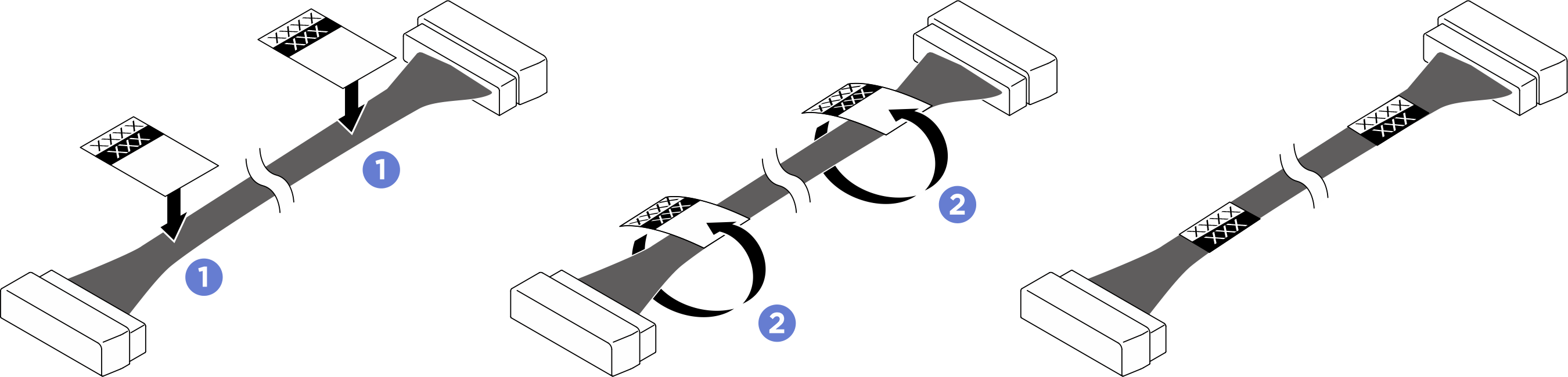
- Route the power cables under the compute tray as illustrated below.
- Route the signal cables over the system board as illustrated below.
- For DPU adapter power cable routing, see DPU adapter power cable routing.
PCIe riser cable routing
Figure 2. PCIe riser cable routing
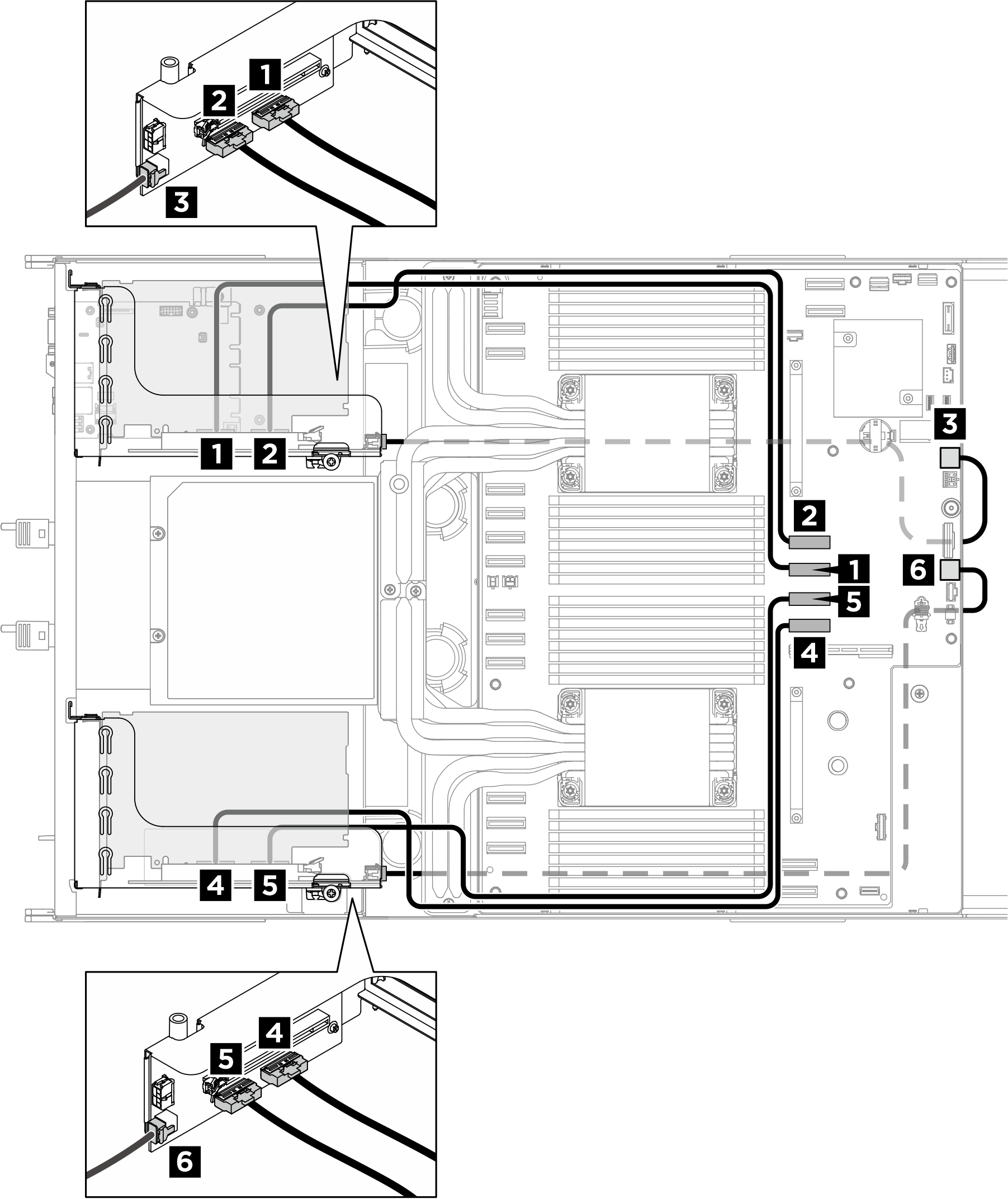
| From | To | Label |
|---|---|---|
| 1 PCIe riser 2 signal connector (MCIO 2) | 2 System board: PCIe Riser 2 signal connectors (MCIO4A) |
|
| 2 PCIe riser 2 signal connector (MCIO 1) | 1 System board: PCIe Riser 2 signal connectors (MCIO4B) |
|
| 3 PCIe Riser 2 power connector (RISER PWR) | 3 System board: PCIe Riser 2 power and sideband connector (BP PWR/SIG 2) |
|
| 4 PCIe riser 1 signal connector (MCIO 2) | 5 System board: PCIe Riser 1 signal connectors (MCIO8B) |
|
| 5 PCIe riser 1 signal connector (MCIO 1) | 4 System board: PCIe Riser 1 signal connectors (MCIO8A) |
|
| 6 PCIe Riser 1 power connector (RISER PWR) | 6 System board: PCIe Riser 1 power and sideband connector (BP PWR/SIG 3) |
|
Give documentation feedback