Integrated diagnostics panel cable routing
Use the section to understand the cable routing for the integrated diagnostics panel.
Note
- If necessary, attach the labels to the end of the cable that connects to the system board.
 Attach the white space portion of the label.
 Wrap the label around the cable and attach it to the white space portion.
Figure 1. Label application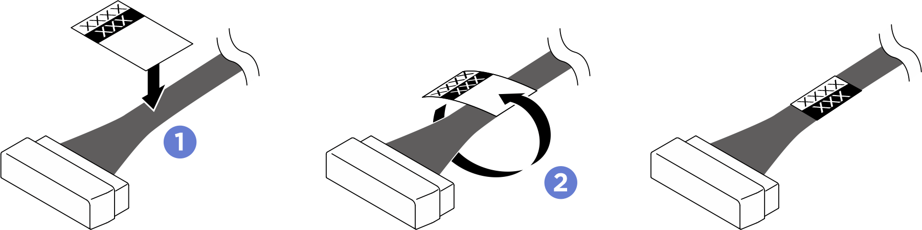
- Pass the cable through the cable holder and baffle assembly, then route it over the system board as illustrated below.
Figure 2. Integrated diagnostics panel cable routing
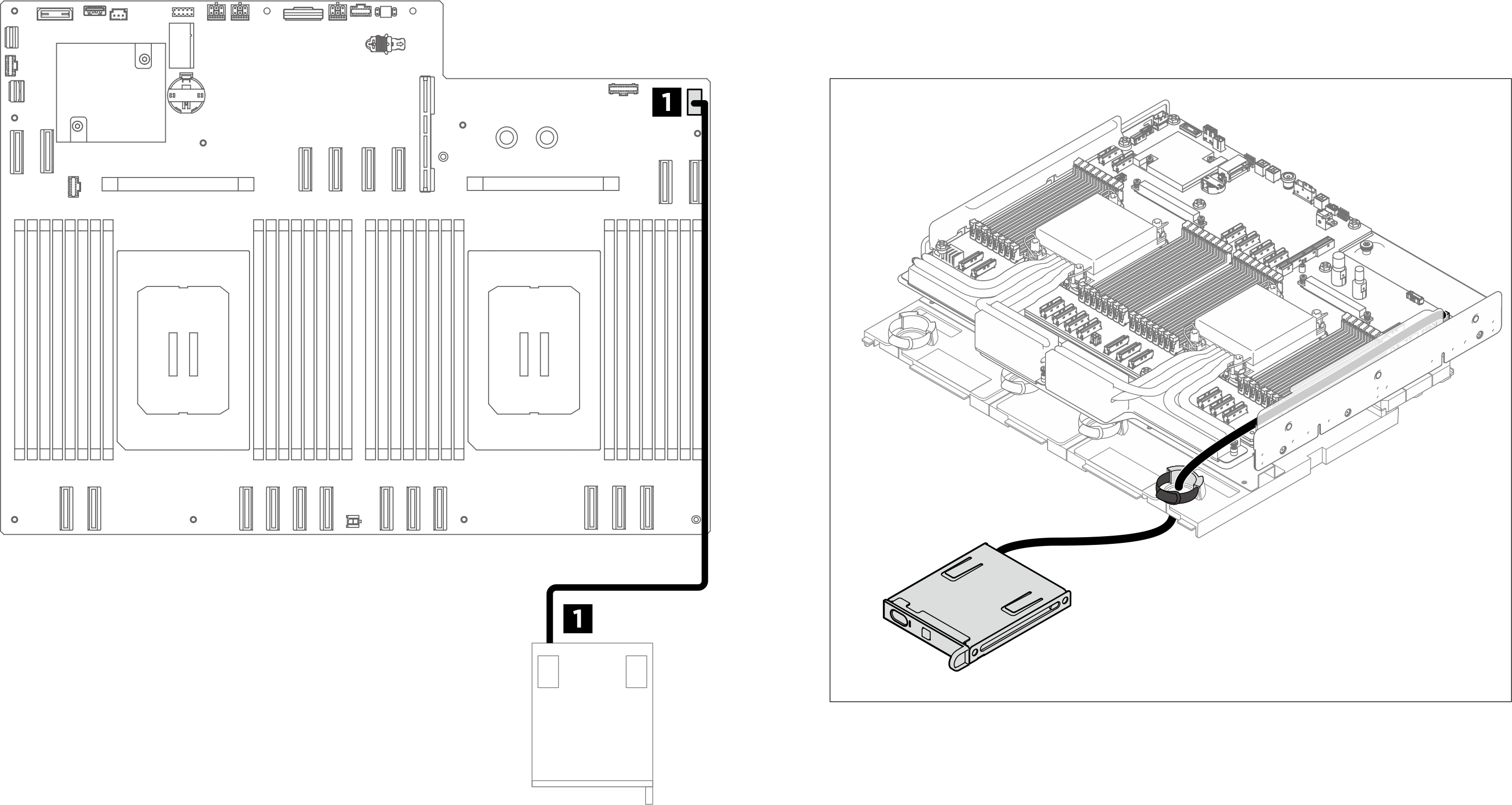
| From | To | Label |
|---|---|---|
| 1 Integrated diagnostics panel cable | 1 System board: Integrated diagnostics panel connector (FRONT IO2) |
|
Give documentation feedback