Fan control board cable routing
Use the section to understand the cable routing for the front or rear fan control board.
Note
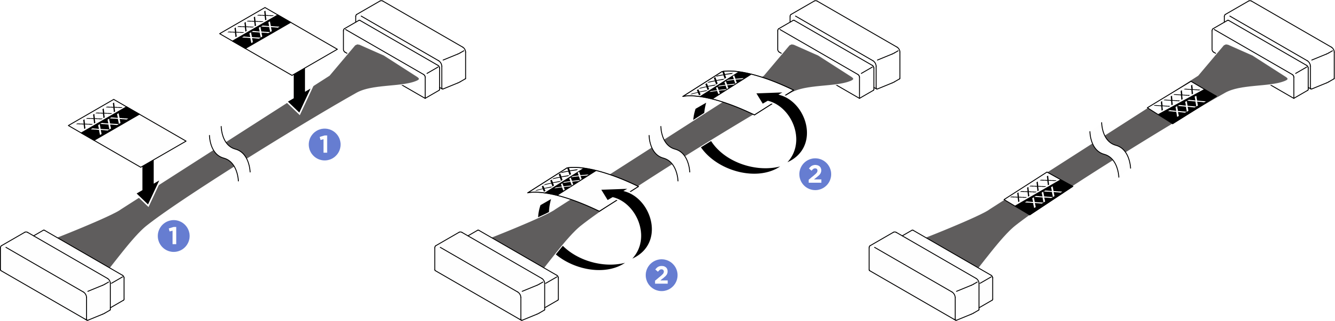
If necessary, attach the labels to both ends of the cables.
 Attach the white space portion of the label to one end of the cable.
 Wrap the label around the cable and attach it to the white space portion.
- Repeat to attach the other label to the opposite end of the cable.
Figure 1. Label application
Based on the location of the fan control board, select the corresponding routing plan:
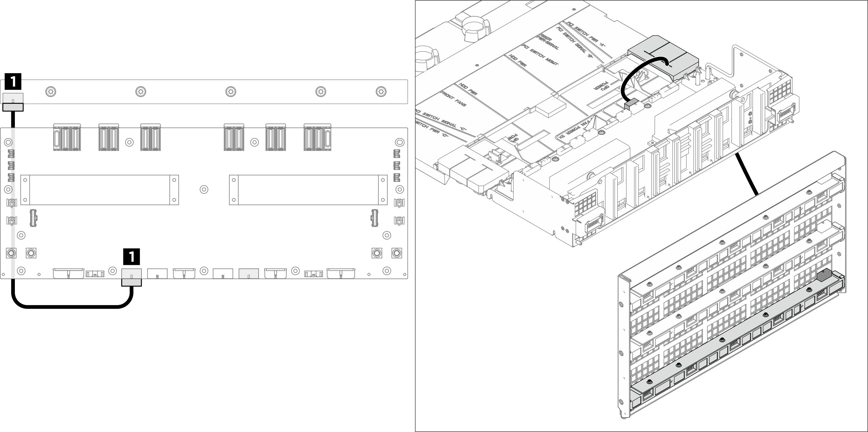
Front fan control board
Note
Pass the cable under the heat pipe at the center, then route it over the system board as illustrated below.
Figure 2. Front fan control board cable routing
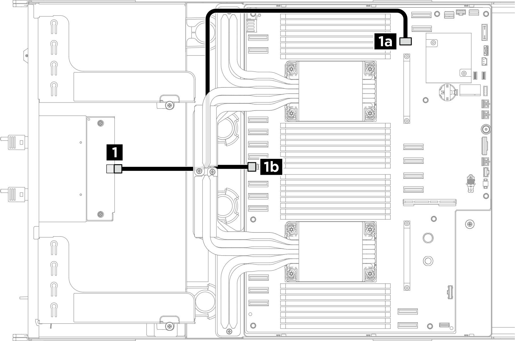
| From | To | Label |
|---|---|---|
| 1 Front fan control board: Power connector | 1a System board: Front fan control board signal connector (BOT FAN BOARD) | N/A |
| 1b System board: Front fan control board power connector (REAR IO PWR) |
Rear top fan control board
Note
- Connect the green cable to the rear top fan control board signal connector (F-FAN PWR) on the power distribution board.
- Pass the cable through the cable holder and baffle assembly, then route it under the compute tray as illustrated below.
Figure 3. Rear top fan control board cable routing
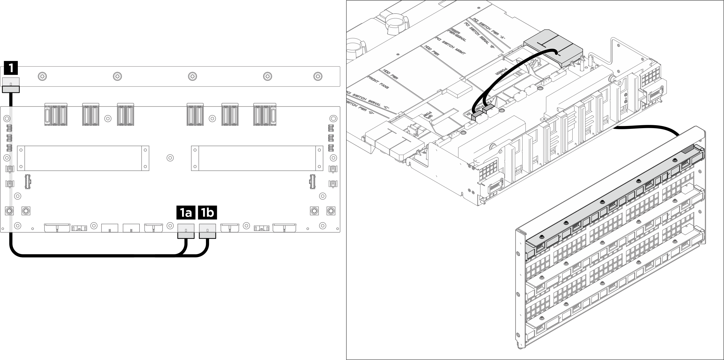
| From | Label | To | Label |
|---|---|---|---|
| 1 Rear top fan control board: Power connector |
| 1a Power distribution board: Rear top fan control board power connector (RADIATOR FAN) (black cable) |
|
| 1b Power distribution board: Rear top fan control board signal connector (F-FAN PWR) (green cable) |
|
Rear middle fan control board
Note
Pass the cable through the cable holder and baffle assembly, then route it under the compute tray as illustrated below.
Figure 4. Rear middle fan control board cable routing
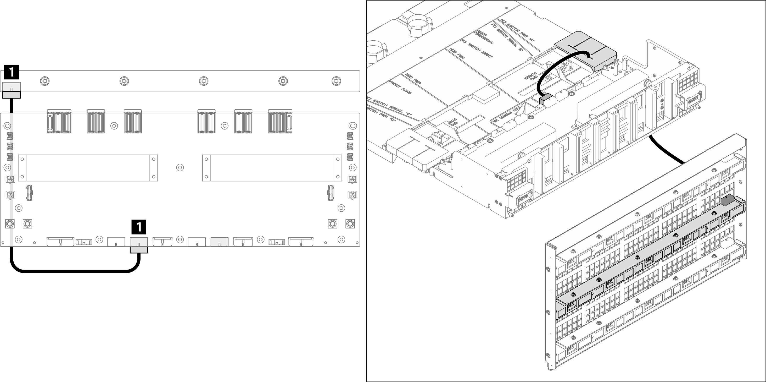
| From | To | Label |
|---|---|---|
| 1 Rear middle fan control board: Power connector | 1 Power distribution board: Rear middle fan control board power connector (R-FAN PWR2) |
|
Rear bottom fan control board
Note
Pass the cable through the cable holder and baffle assembly, then route it under the compute tray as illustrated below.
Figure 5. Rear bottom fan control board cable routing
| From | To | Label |
|---|---|---|
| 1 Rear bottom fan control board: Power connector | 1 Power distribution board: Rear bottom fan control board power connector (R-FAN PWR1) |
|
Give documentation feedback