System board connectors for cable routing
The following illustrations show the internal connectors on the system board that are used for internal cable routing.
Figure 1. System board connectors for cable routing
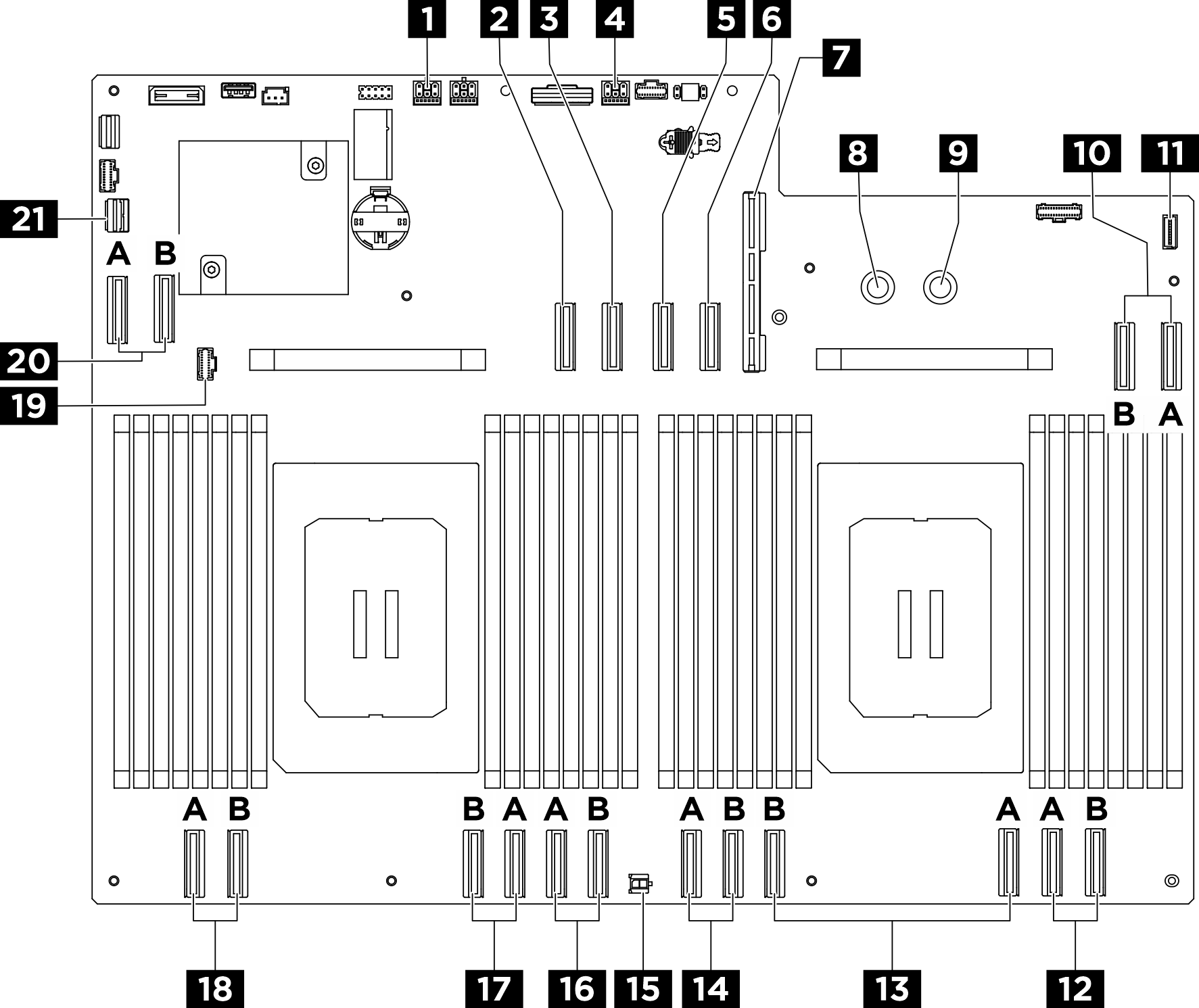
| 1 PCIe Riser 2 power and sideband connector (BP PWR/SIG 2) | 2 PCIe Riser 2 signal connector (MCIO4B) |
| 3 PCIe Riser 2 signal connector (MCIO4A) | 4 PCIe Riser 1 power and sideband connector (BP PWR/SIG 3) |
| 5 PCIe Riser 1 signal connector (MCIO8A) | 6 PCIe Riser 1 signal connector (MCIO8B) |
| 7 System I/O board connector (DC-SCM) | 8 Ground (-) connector (PSU_GND) |
| 9 12V (+) connector (PSU_P12V) | 10 MCIO connector 7 (MCIO7A/MCIO7B) |
| 11 Integrated diagnostics panel connector (FRONT IO2) | 12 MCIO connector 6 (MCIO6A/MCIO6B) |
| 13 MCIO connector 5 (MCIO5A/MCIO5B) | 14 MCIO connector 10 (MCIO10A/MCIO10B) |
| 15 Front fan control board power connector (Rear IO PWR) | 16 MCIO connector 3 (MCIO3A/MCIO3B) |
| 17 MCIO connector 2 (MCIO2A/MCIO2B) | 18 MCIO connector 1 (MCIO1A/MCIO1B) |
| 19 Front fan control board signal connector (BOT FAN BOARD) | 20 MCIO connector 9 (MCIO9A/MCIO9B) |
| 21 PCIe switch sideband connector (PCIE SW SIDEBAND) |
Give documentation feedback