Install the GPU complex
Follow instructions in this section to install the GPU complex. The procedure must be executed by a trained technician.
About this task
S036
 |  |
| 18 - 32 kg (39 - 70 lb) | 32 - 55 kg (70 - 121 lb) |
CAUTION
Use safe practices when lifting.
Attention
- Read Installation Guidelines and Safety inspection checklist to ensure that you work safely.
- Touch the static-protective package that contains the component to any unpainted metal surface on the server; then, remove it from the package and place it on a static-protective surface.
- Two people and one lifting device on site that can support up to 400 lb (181 kg) are required to perform this procedure. If you do not already have a lifting device available, Lenovo offers the Genie Lift GL-8 material lift that can be purchased at Data Center Solution Configurator. Make sure to include the Foot-release brake and the Load Platform when ordering the Genie Lift GL-8 material lift.
Note
Make sure you have the required tools listed below available to properly replace the component:
- One torque screwdriver
- One Torx T15 extended bit (300 mm long)
Firmware and driver download: You might need to update the firmware or driver after replacing a component.
Go to Drivers and Software download website for ThinkSystem SR680a V3 to see the latest firmware and driver updates for your server.
Go to Update the firmware for more information on firmware updating tools.
Procedure
- (Optional) Remove the new GPU complex from the package box.
 Extend the two handles on both sides of the GPU baseboard.
 Grasp the center of both handles simultaneously and remove the GPU complex vertically out of the package box.
Attention- Make sure two people stand on either side of the GPU complex, and lift it by holding the two handles. Do not lift the GPU complex using only one handle.
- Apply even pressure to the center of the handles. Avoid applying force to just one end of a handle, as this can cause it to rotate or be damaged.
- Maintain a smooth and vertical motion. Do not apply side force to the top of the handles.
- Ensure both handles remain at the same height during the handling process.
Figure 1. Removing the GPU complex from the package box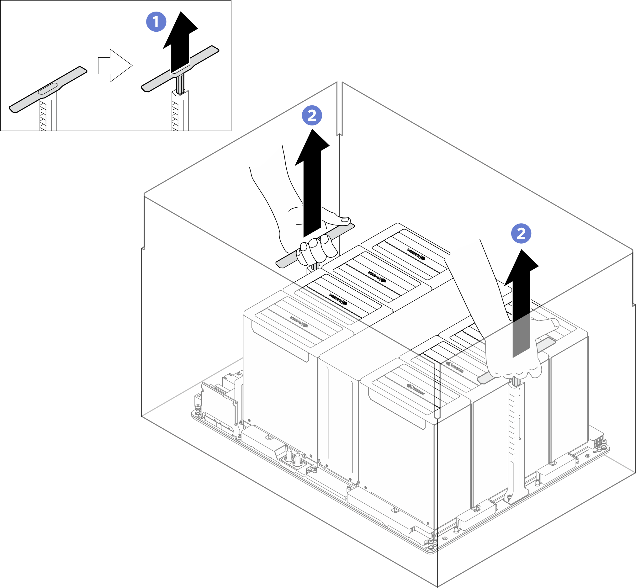
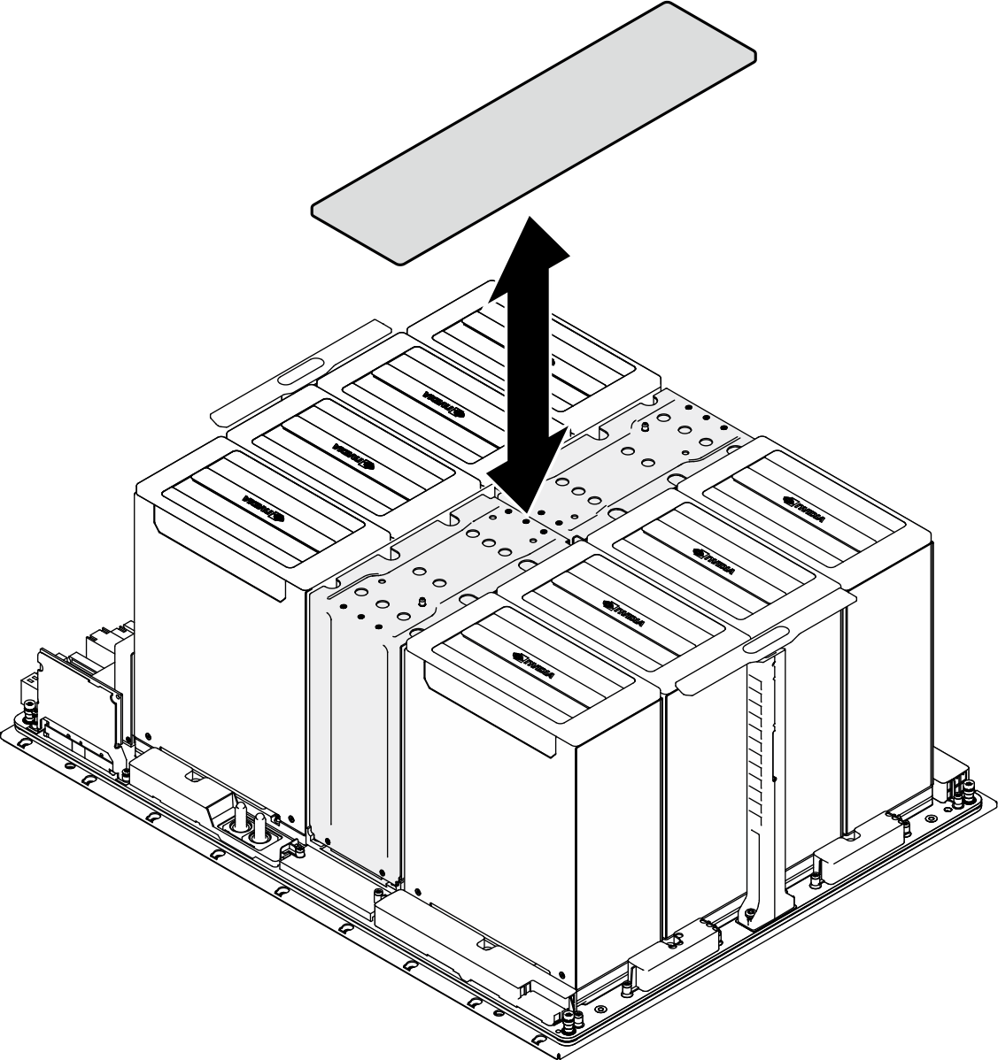
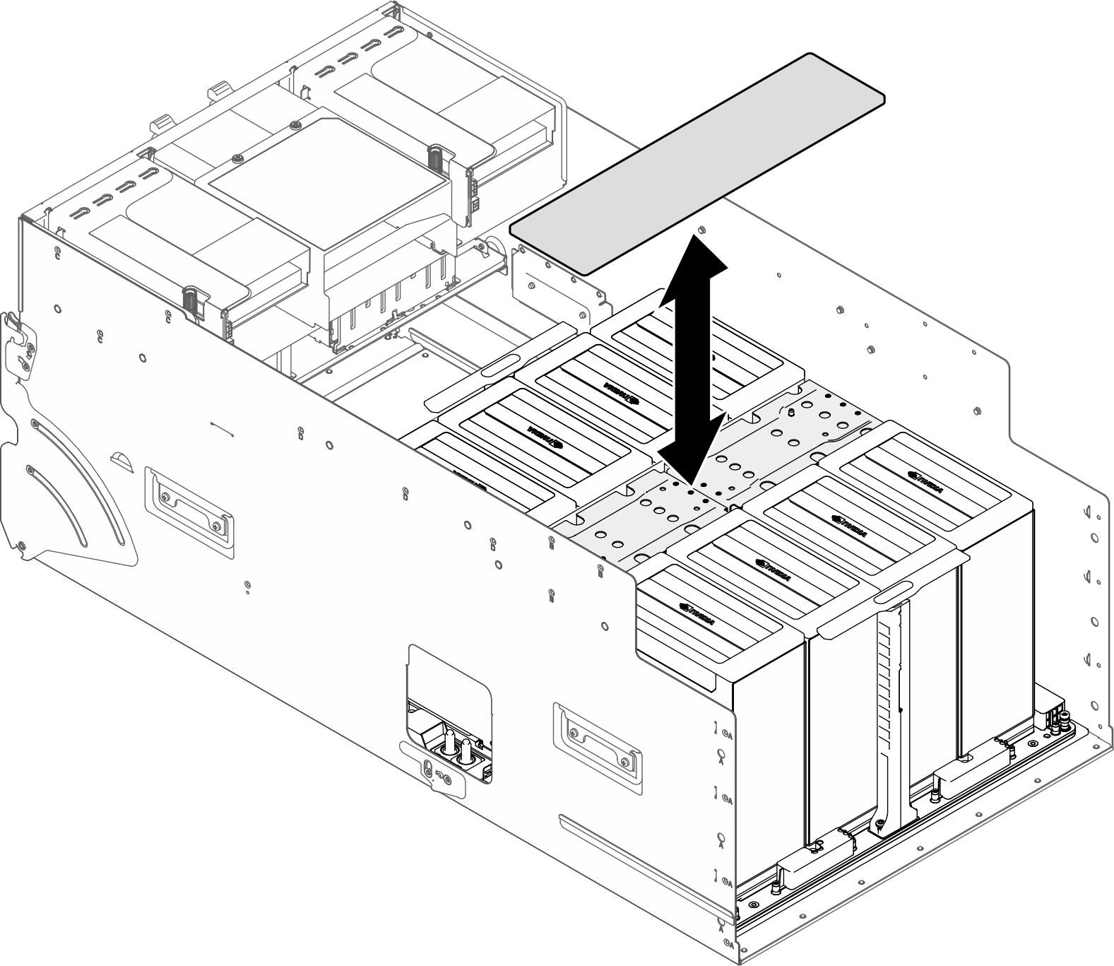
- Remove the cover from the NVSwitch heat sink.Figure 2. NVSwitch heat sink cover removal
- Install the GPU complex.
- Grasp the center of both handles (1) simultaneously in the orientation as illustrated. Align the GPU complex with the standoffs on the adapter plate, then gently lower it into position.
- Push the two handles (1) down.
Attention- Make sure two people stand on either side of the GPU complex, and lift it by holding the two handles. Do not lift the GPU complex using only one handle.
- Apply even pressure to the center of the handles. Avoid applying force to just one end of a handle, as this can cause it to rotate or be damaged.
- Maintain a smooth and vertical motion. Do not apply side force to the top of the handles.
- Ensure both handles remain at the same height during the handling process.
Figure 3. GPU complex installation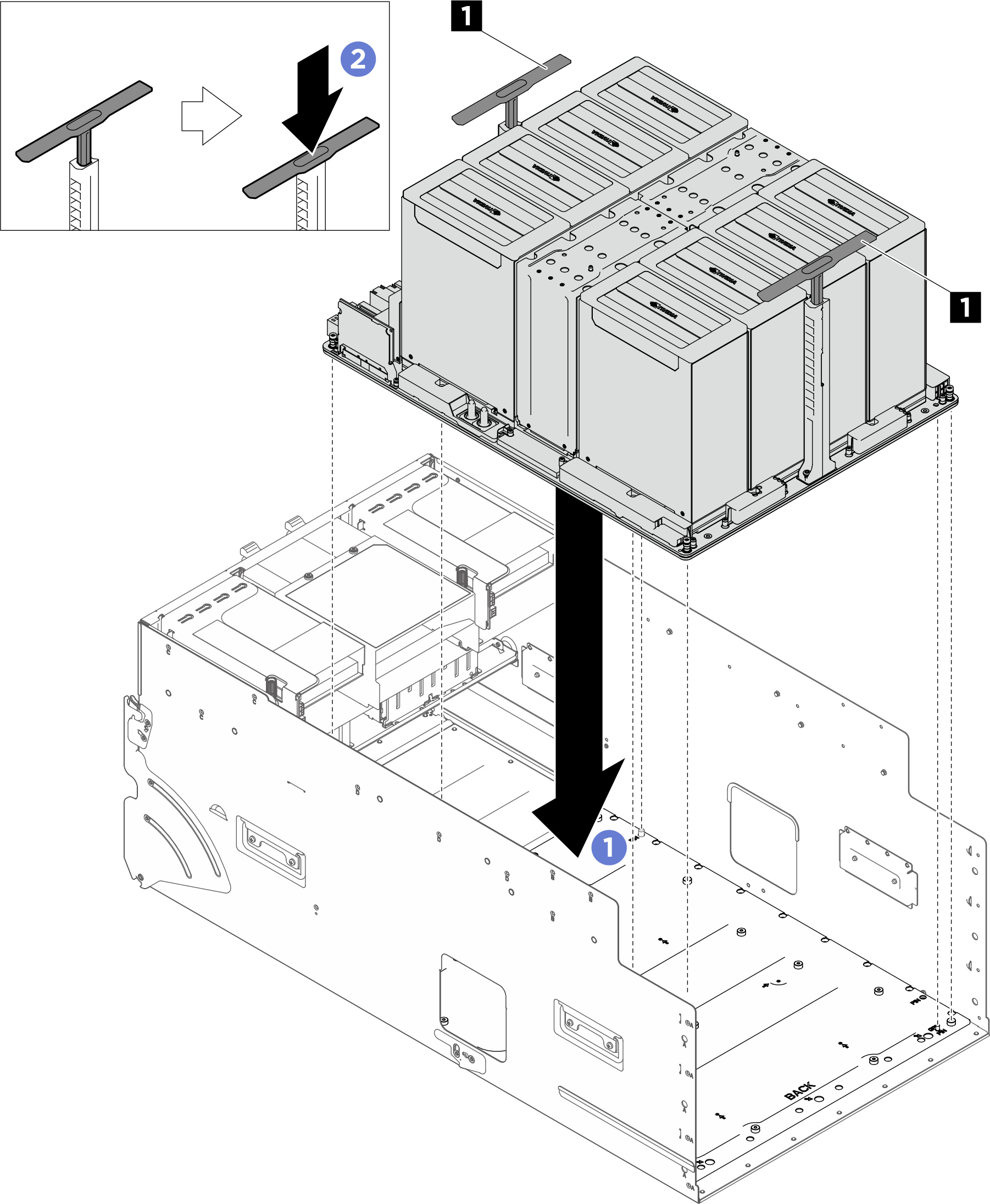
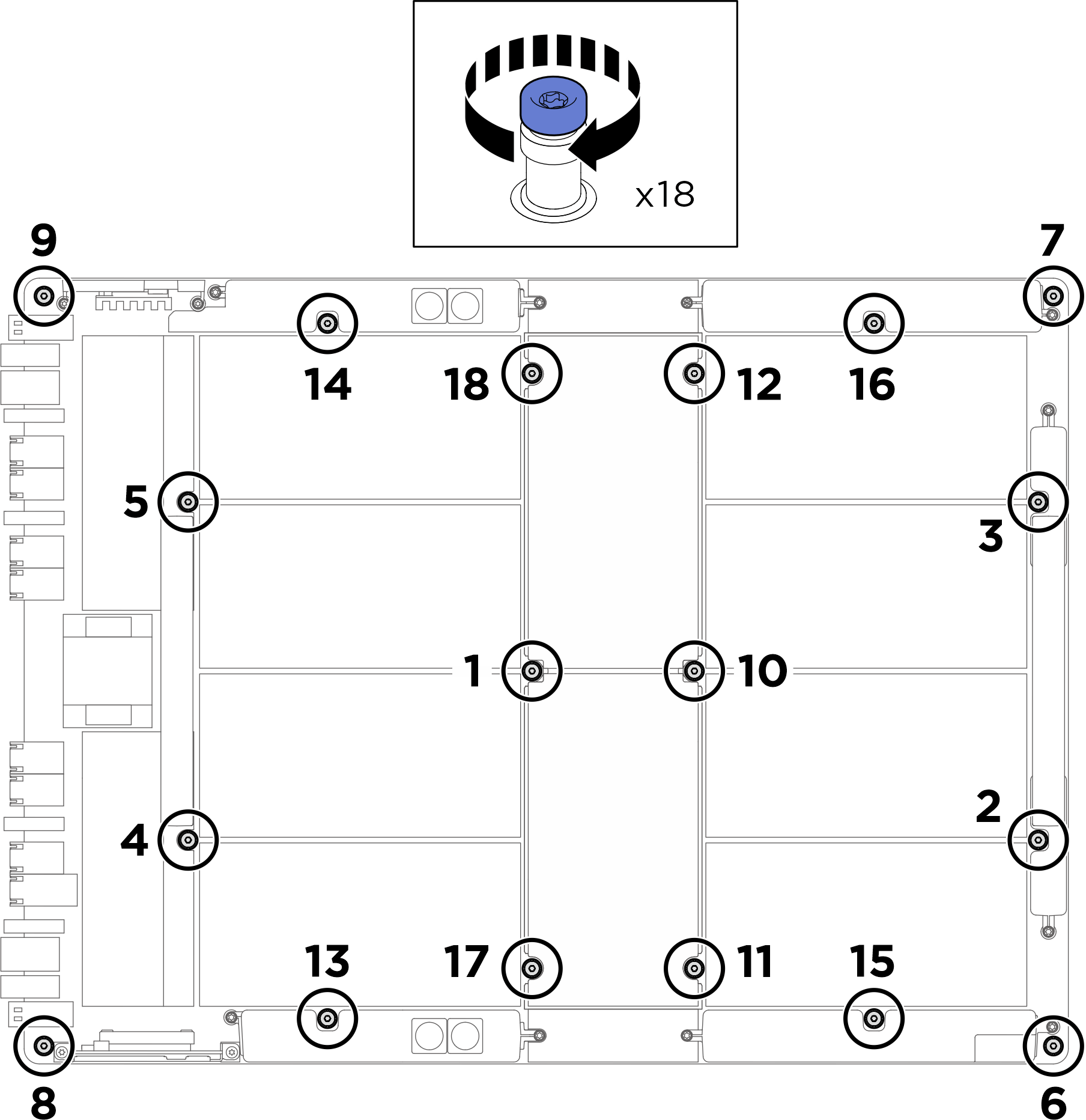
- Follow the sequence shown in the illustration below to fasten the eighteen Torx T15 captive screws to secure the GPU complex.ImportantDo not overtighten the screws to avoid damage.NoteLoosen or tighten the screws with a torque screwdriver set to the proper torque. For reference, the torque required for the screws to be fully loosen or tighten is 0.6±0.024 newton-meters, 5.3±0.212 inch-pounds.Figure 4. Screw installation
- Place the cover onto the NVSwitch heat sink until it is securely seated.Figure 5. NVSwitch heat sink cover installation
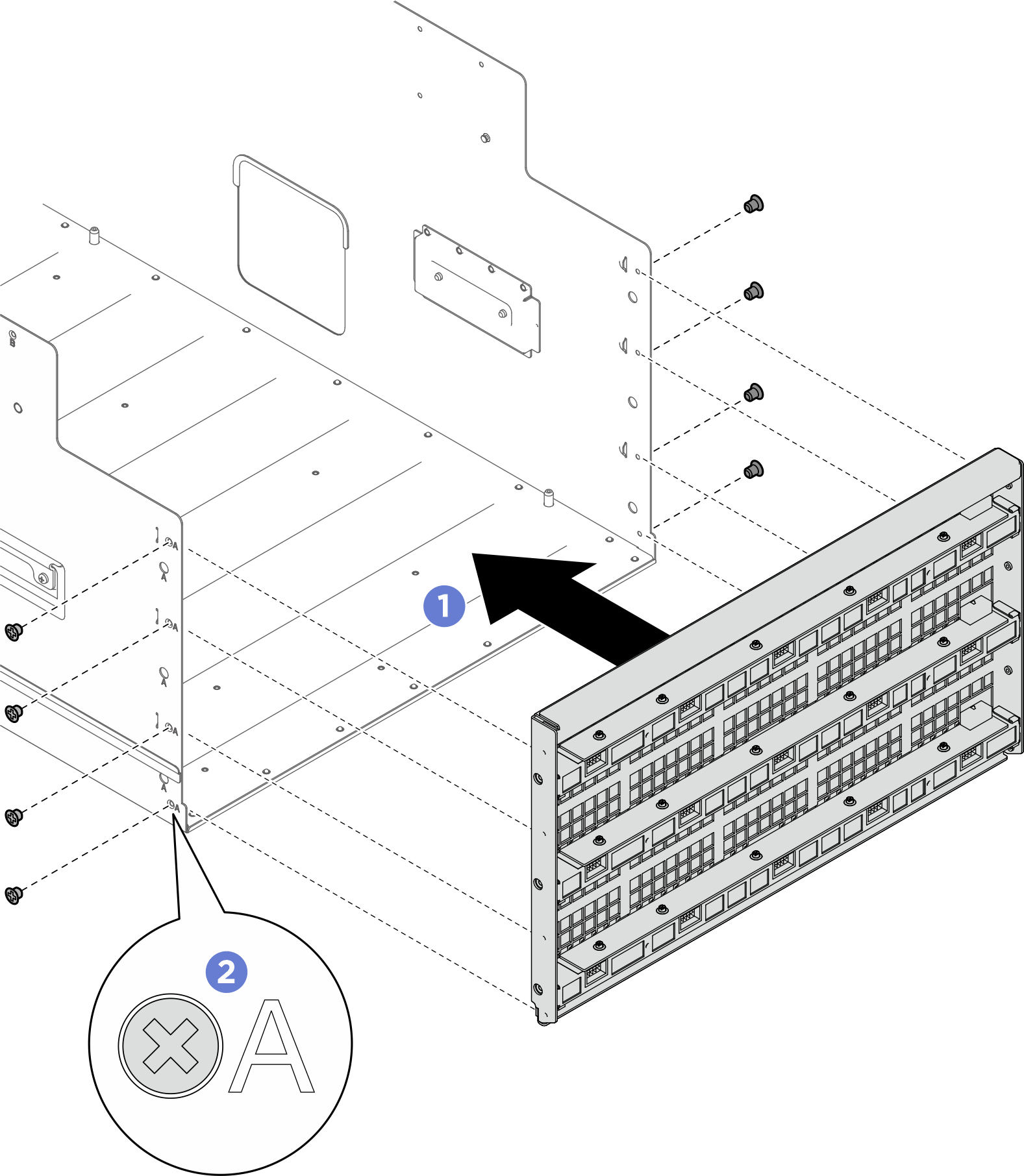
- Install the bulkhead.
- Hold the bulkhead in the correct orientation as illustrated, and slide it into the system shuttle.
- Locate the eight screw holes marked with A on both sides of the system shuttle; then, fasten the eight screws to secure the bulkhead.
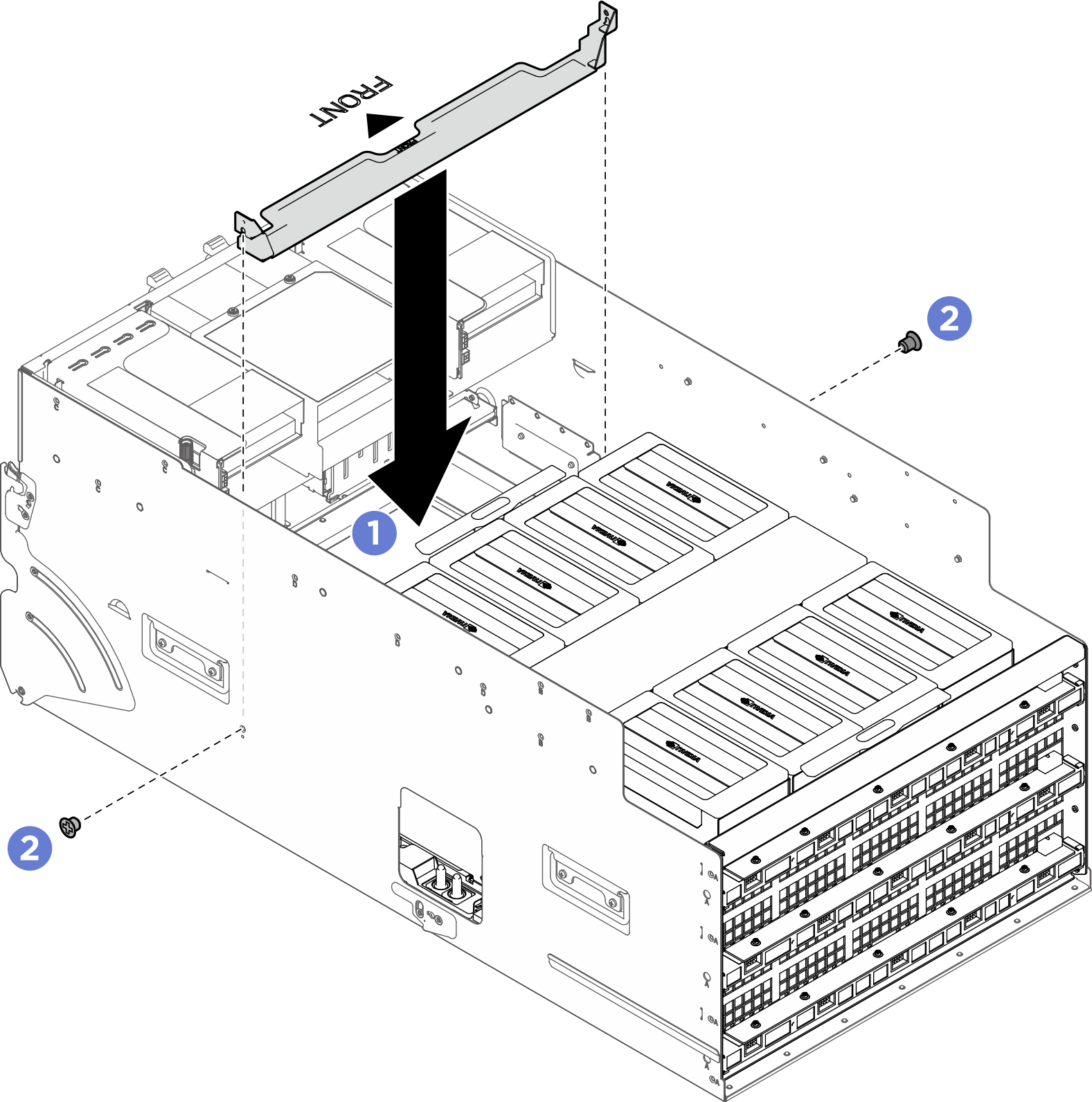
- Install the support bracket.
- Hold the bracket in the correct orientation as illustrated, and lower it into the system shuttle.
- Fasten the two screws to secure the support bracket.
- Push the PCIe switch shuttle fully into the system shuttle.
- Press the two front lock latches on both sides of the PCIe switch shuttle.
- Push the PCIe switch shuttle fully into the system shuttle.
 Rotate the two release levers until they lock into place.Figure 6. PCIe switch shuttle installation
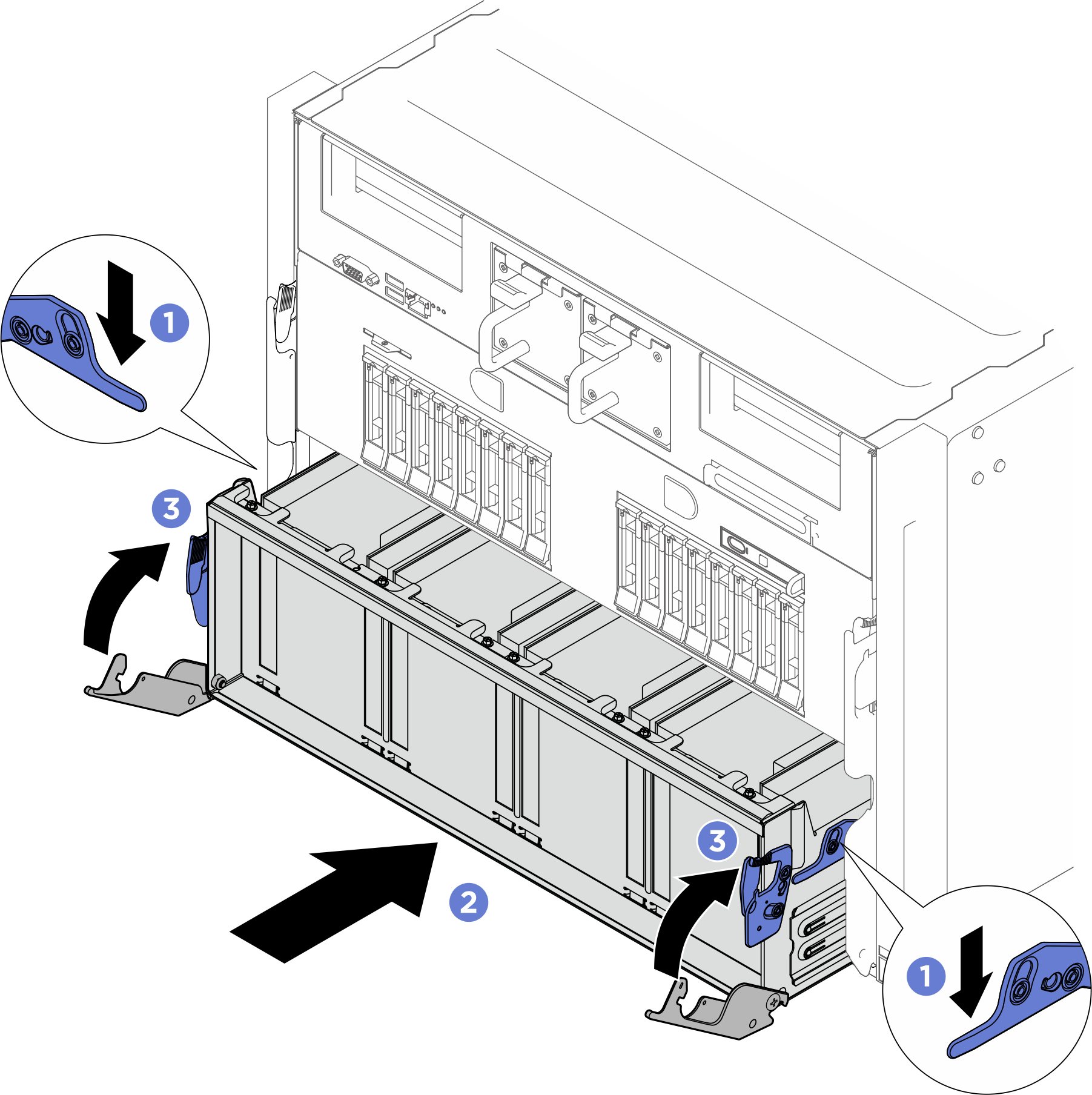
After you finish
- Reinstall all the GPU air ducts. See Install a GPU air duct.
- Reconnect the cables to the GPU baseboard. See GPU baseboard cable routing for more information.
- Reinstall the power complex. See Install the power complex.
- Reinstall the cable holder frame and baffle assembly. See Install the cable holder frame and baffle assembly.
- Reinstall the compute tray. See Install the compute tray.
- Reinstall the system shuttle. See Install the system shuttle.
- Complete the parts replacement. See Complete the parts replacement.
Give documentation feedback