Install the Lenovo Processor Neptune Core Module
Follow the instructions in this section to install the Processor Neptune® Core Module.
This task must be operated by trained technicians that are certified by Lenovo Service. Do not attempt to remove or install the part without proper training and qualification.
Contact Lenovo Professional Services team for help when installing the part for the first time.
Make sure you have the water loop shipping bracket available before performing this task.
About this task
Read Installation Guidelines and Safety inspection checklist to ensure that you work safely.
Power off the server and peripheral devices and disconnect the power cords and all external cables. See Power off the server.
Prevent exposure to static electricity, which might lead to system halt and loss of data, by keeping static-sensitive components in their static-protective packages until installation, and handling these devices with an electrostatic-discharge wrist strap or other grounding system.
- Each processor socket must always contain a cover or a cold plate. When removing or installing a cold plate assembly, protect empty processor sockets with a cover.
- Do not touch the processor socket or processor contacts. Processor-socket contacts are very fragile and easily damaged. Contaminants on the processor contacts, such as oil from your skin, can cause connection failures.
- Do not allow the thermal grease on the processor or cold plate to come in contact with anything. Contact with any surface can compromise the thermal grease, rendering it ineffective. Thermal grease can damage components, such as the electrical connectors in the processor socket.
| Torque screwdriver type list | Screw Type |
|---|---|
| Torx T30 head screwdriver | Torx T30 screw |
Procedure
- Install the processor in the new carrier. Note
- If you are replacing the processor and reusing the cold plate, use the new carrier that comes with the new processor.
- If you are replacing the cold plate and reusing the processor, and if the new cold plate comes with processor carriers, make sure to use the same type of carrier as the one you discarded.
Figure 1. Processor carrier installation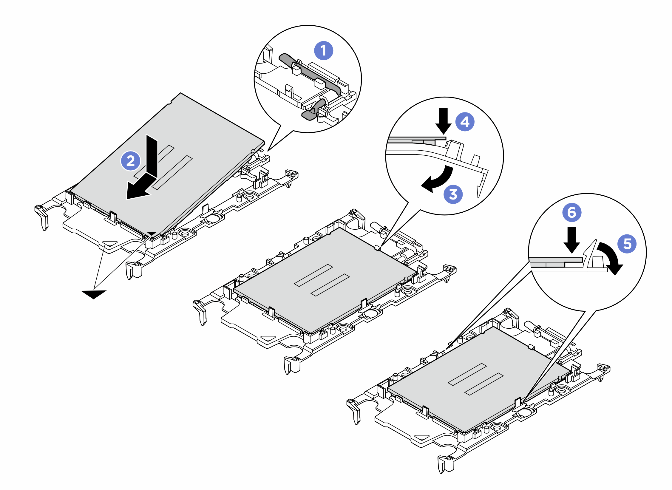 NoteTo prevent the processor from falling out of the carrier, keep the processor-contact side up and hold the processor-carrier assembly by the sides of the carrier.
 Make sure the handle on the carrier is in the closed position.
 Align the processor on the new carrier so that the triangular marks align; then, insert the marked end of the processor into the carrier.
 Hold the inserted end of the processor in place; then, pivot the unmarked end of the carrier down and away from the processor.
 Press the processor and secure the unmarked end under the clip on the carrier.
 Carefully pivot the sides of the carrier down and away from the processor.
 Press the processor and secure the sides under the clips on the carrier.
- Apply thermal grease.
- If you are replacing the cold plate and reusing the processor, a new cold plate comes with thermal grease and you do not need to apply new thermal grease.NoteTo ensure the best performance, check the manufacturing date on the new cold plate and make sure it does not exceed two years. Otherwise, wipe off the existing thermal grease and apply new thermal grease.
- If you are replacing the processor and reusing the cold plate, do the following steps to apply thermal grease:
- If there is any old thermal grease on the cold plate, wipe off the thermal grease with an alcohol cleaning pad.
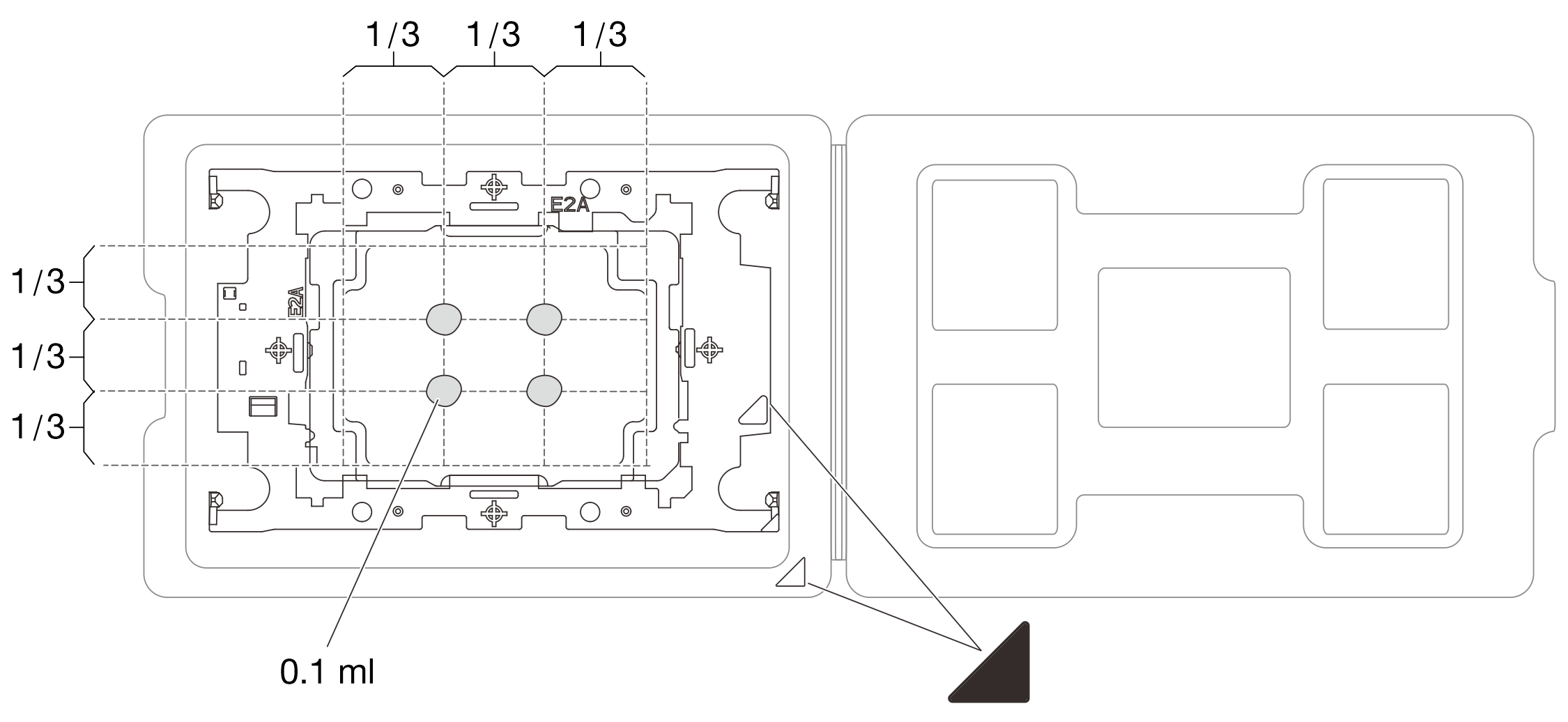
- Carefully place the processor and carrier in the shipping tray with the processor-contact side down. Make sure the triangular mark on the carrier is oriented in the shipping tray as shown below.
- Apply the thermal grease on the top of the processor with syringe by forming four uniformly spaced dots, while each dot consists of about 0.1 ml of thermal grease.Figure 2. Thermal grease application with processor in shipping tray
- If you are replacing the cold plate and reusing the processor, a new cold plate comes with thermal grease and you do not need to apply new thermal grease.
- Assemble the processor and cold plate.Figure 3. Installing processor to cold plate
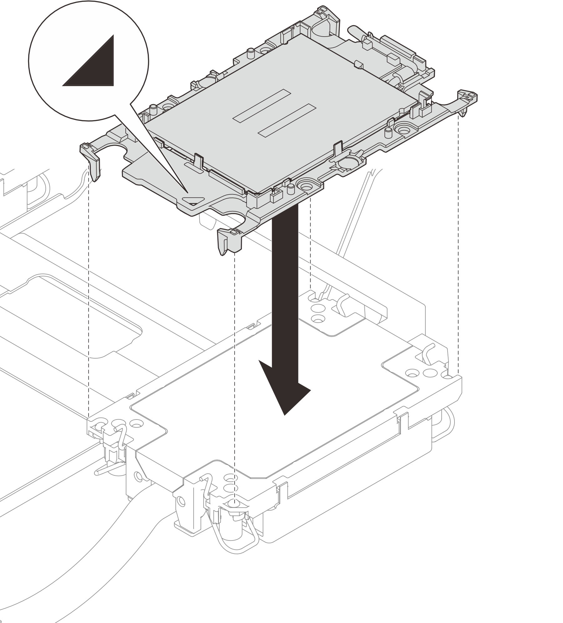
- Align the triangular mark on the processor carrier and processor with the triangular mark on the cold plate.
- Install the processor-carrier onto the cold plate.
- Press the carrier into place until the clips at all four corners engage. Visually inspect to make sure that there is no gap between the processor carrier and the cold plate.
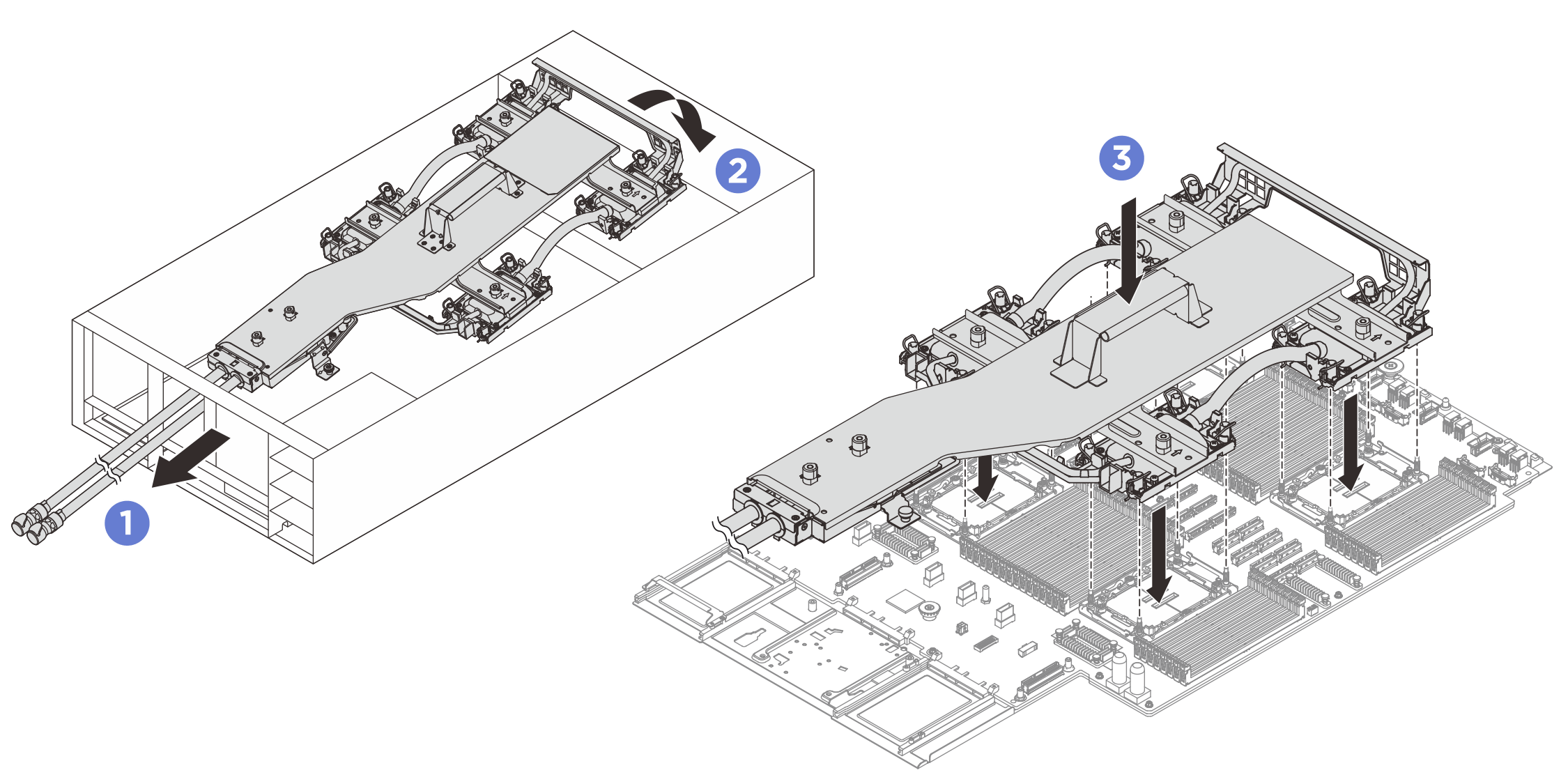
- Install the cold plate assembly.NoteIf the server has only two processors installed, generally processors 1 and 2, it is required to install covers to the empty sockets of processors 3 and 4 before proceeding with further installation.Figure 4. Installing cold plate assembly
 Note
Note- Do not touch the contacts on the bottom of the processor.
- Keep the processor socket clean from any object to prevent possible damages.
- Hold the handle on the cold plate assembly and gently insert the hoses into the opening on the rear of the chassis.
- Lower the front of the cold plate assembly and align the four Torx T30 nuts on each cold plate with the corresponding threaded posts of the processor socket.
- Insert the cold plate assembly into the processor socket.
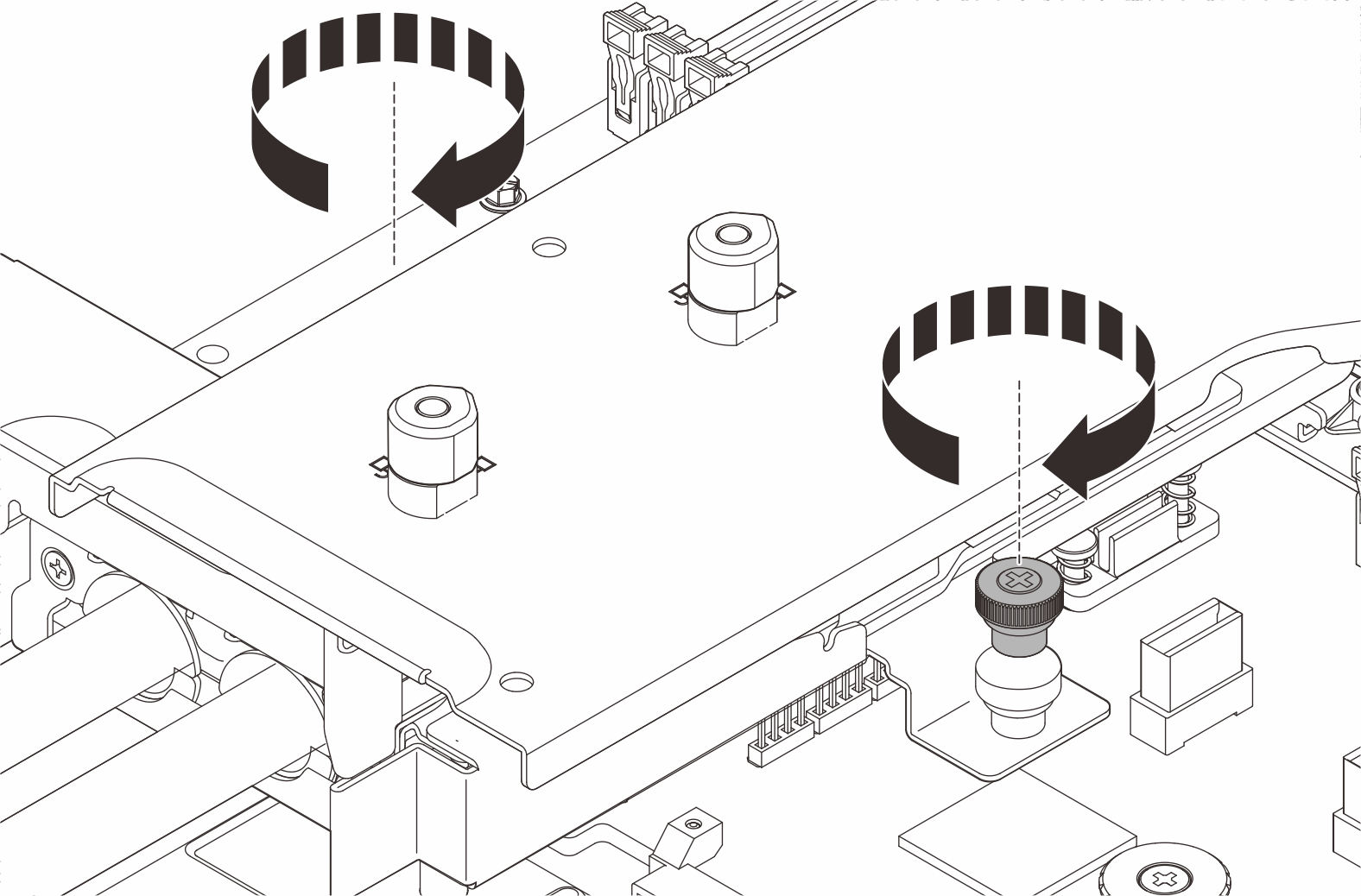
- Tighten the thumbscrews to secure the cold plate assembly. Use a screwdriver if necessary.Figure 5. Installing cold plate assembly
- Tighten the Torx T30 nuts on the cold plate assembly.Figure 6. Tightening Torx T30 nuts
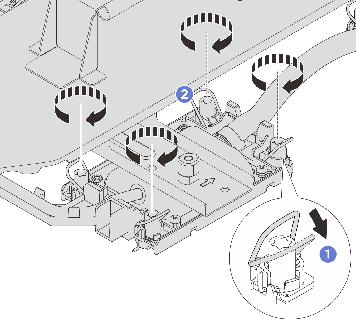
- Rotate the anti-tilt wire bails outward until they engage with the hooks in the socket.
- Fully tighten the Torx T30 nuts in the installation sequence shown on the cold plate assembly label. Tighten the screws until they stop; then, visually inspect to make sure that there is no gap between the screw shoulder beneath the cold plate assembly and the processor socket. (For reference, the torque required to fully tighten the nuts is 10 +/– 2.0 lbf-in, 1.1 +/– 0.2 N-m.)
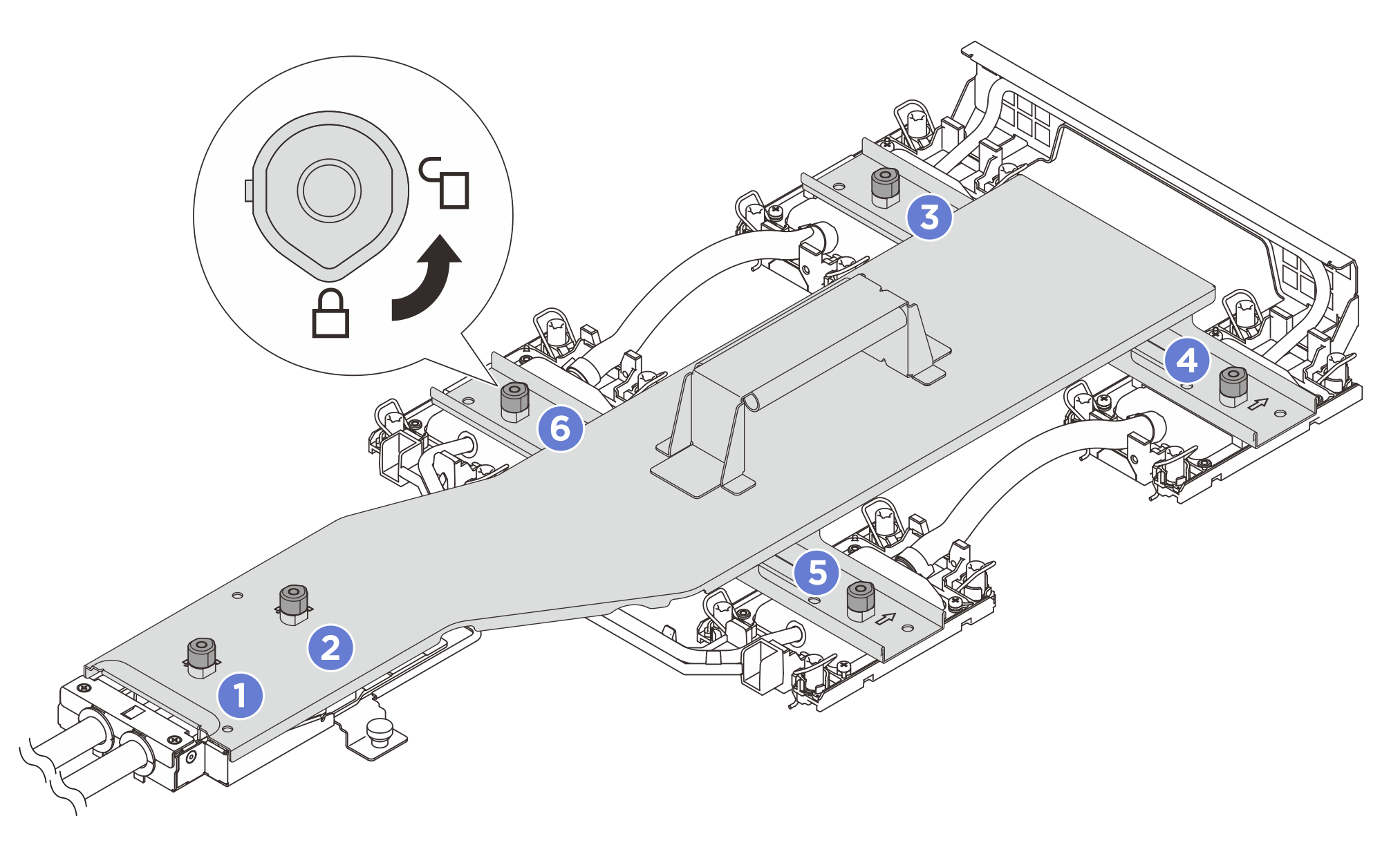
- Rotate all plungers counterclockwise to the unlocked position in the removal sequence shown on the carrier label.Figure 7. Loosening cold plate carrier
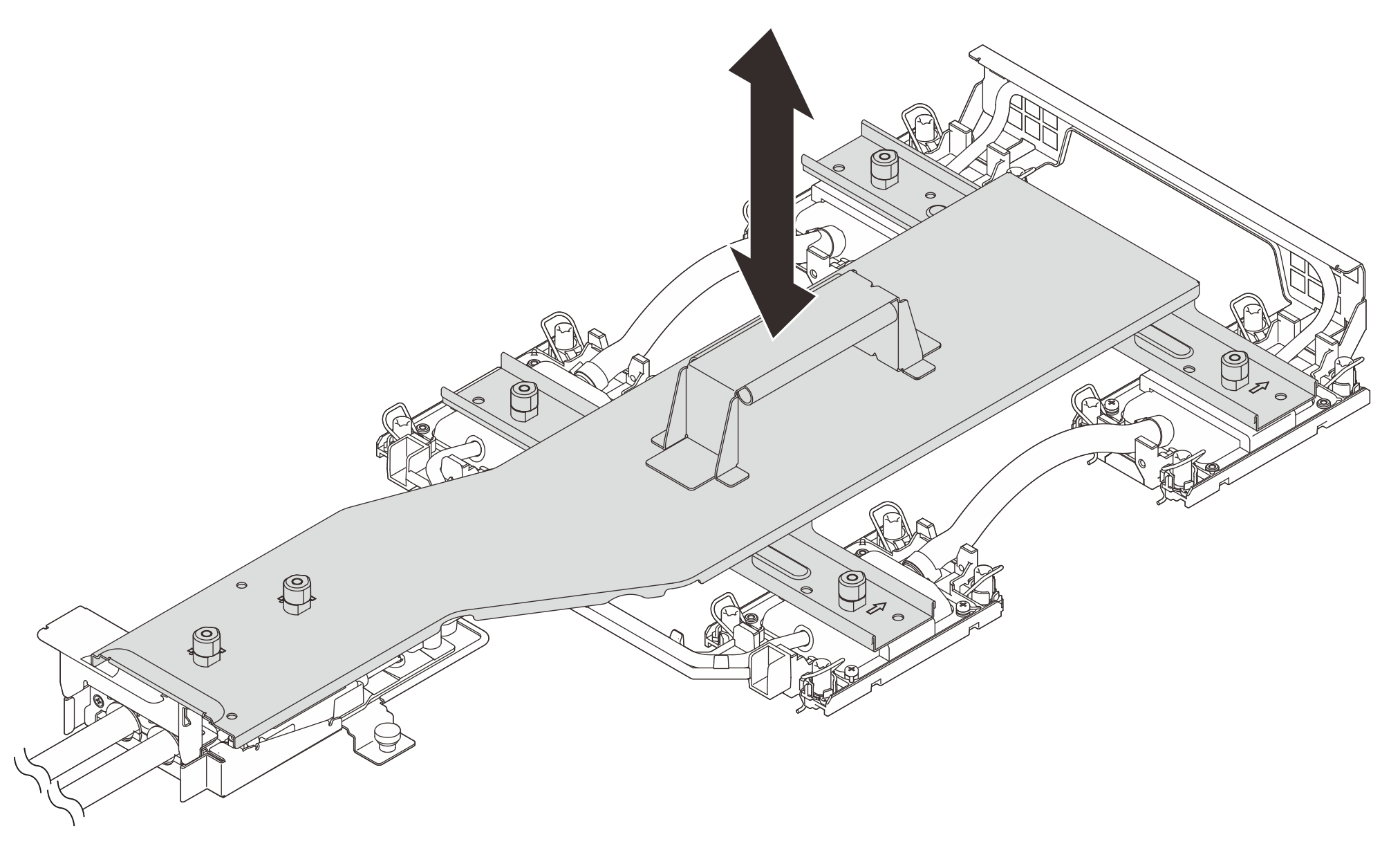
- Remove the cold plate carrier from the cold plate assembly.Figure 8. Removing cold plate carrier
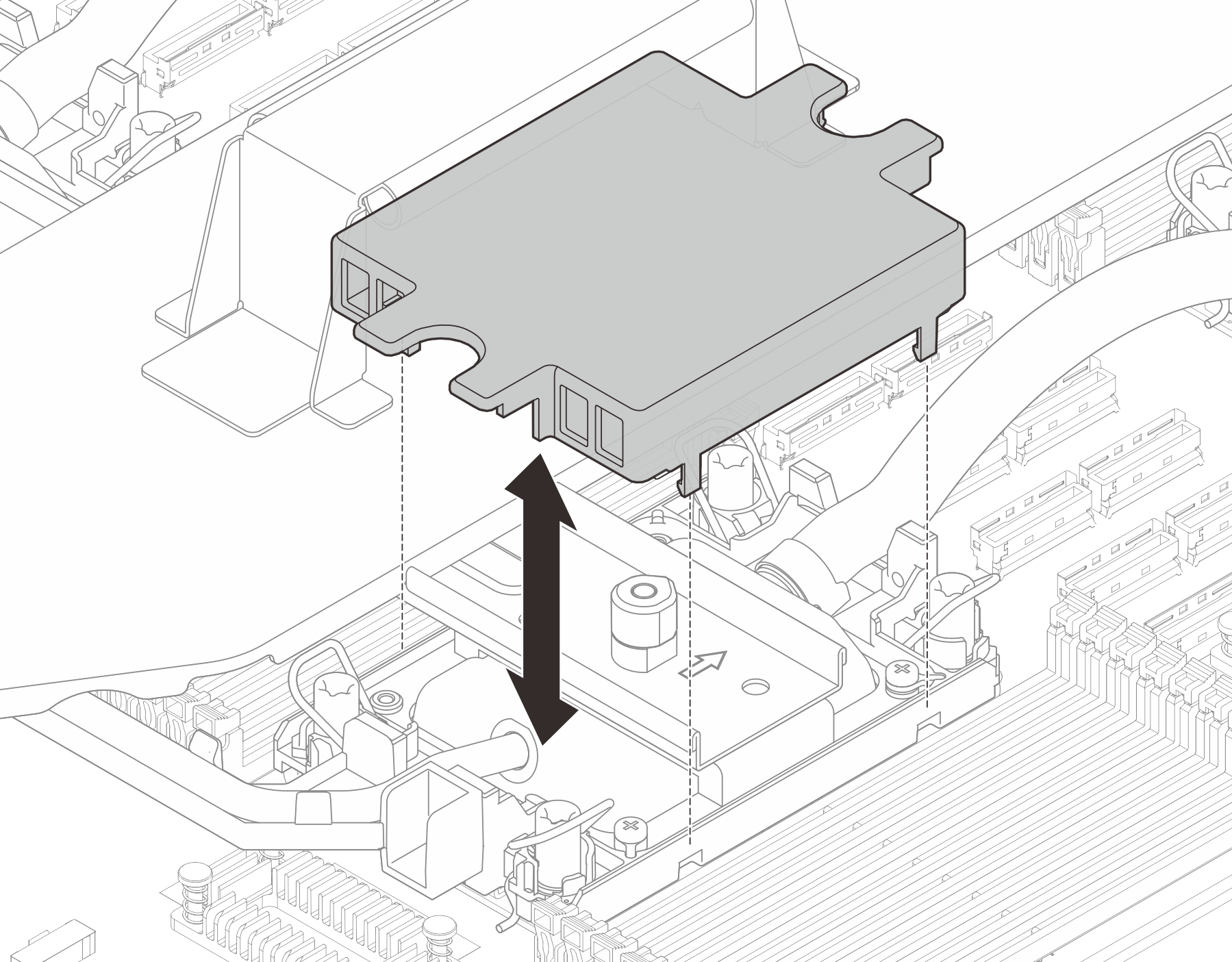
- Install the cold plate covers.Figure 9. Installing cold plate covers
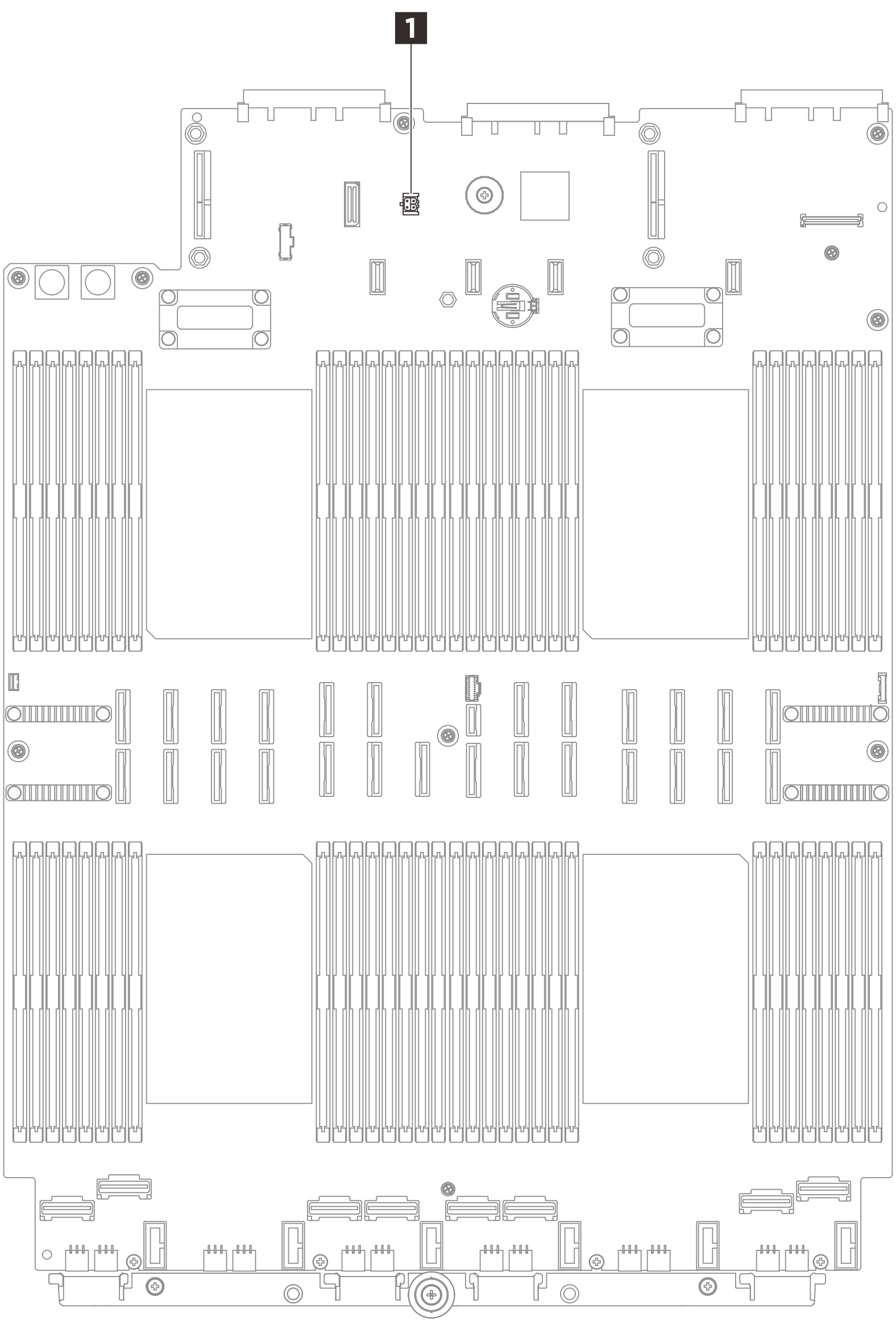
- Connect the leakage detection sensor module cable to the connector 1 on the system board assembly.Figure 10. Connecting leakage detection sensor module
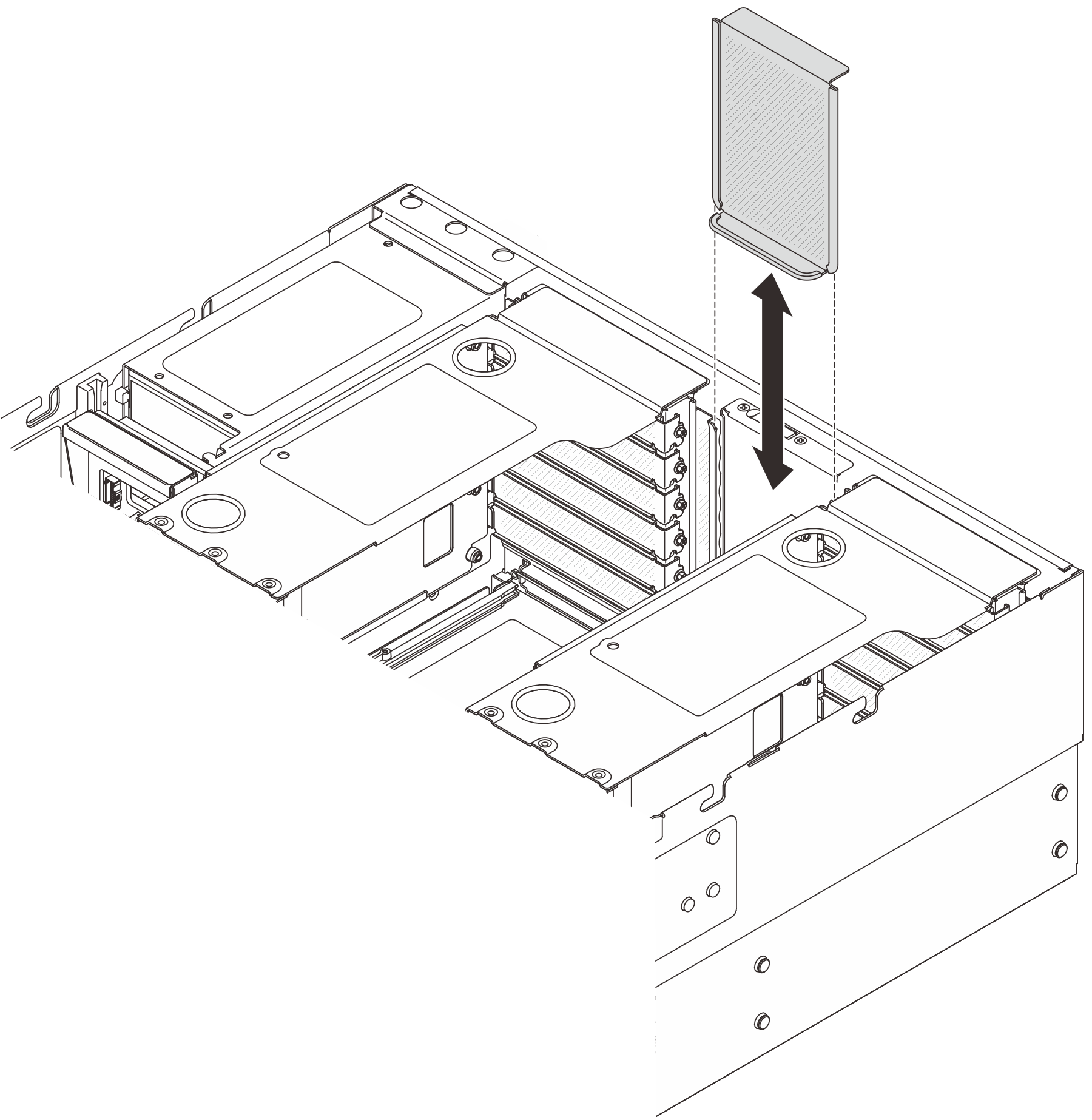
- Install the riser filler.Figure 11. Installing riser filler
After you finish
Reinstall the memory modules. See Install a memory module.
Reinstall the rear air baffle. See Install the rear air baffle.
Reinstall the PCIe risers. See Install the PCIe riser.
Reinstall the crossbar. See Install the crossbar.
Reinstall the front air baffle. See Install the front air baffle.
Reinstall the fans and the fan cage. See Install a fan and Install the fan cage.
Reinstall the rear top cover. See Install the rear top cover.
Reinstall the front top cover. See Install the front top cover.
- Install the server into the rack. See Server replacement.
- Install the quick connect plugs to the manifolds. See Install the manifold (in-rack system) or Install the manifold (in-row system).
- Complete the parts replacement. See Complete the parts replacement.
Demo video