Remove the front USB/VGA assembly
The front USB/VGA assembly is in the lower compute tray that is accessed from the front of the server. After removing the lower tray, disconnect the front USB/VGA assembly cables from the lower system board; then, remove the two screws and remove the operator panel.

Remove the front cover. See Remove the front cover.
Remove the lower compute tray. See Remove a compute tray.
If an upper system board or system board filler is installed in the tray, remove it. See Remove a system board.
Remove the lower fan cage. See Remove a fan cage (lower tray).
Complete the following steps to remove the front USB/VGA assembly.
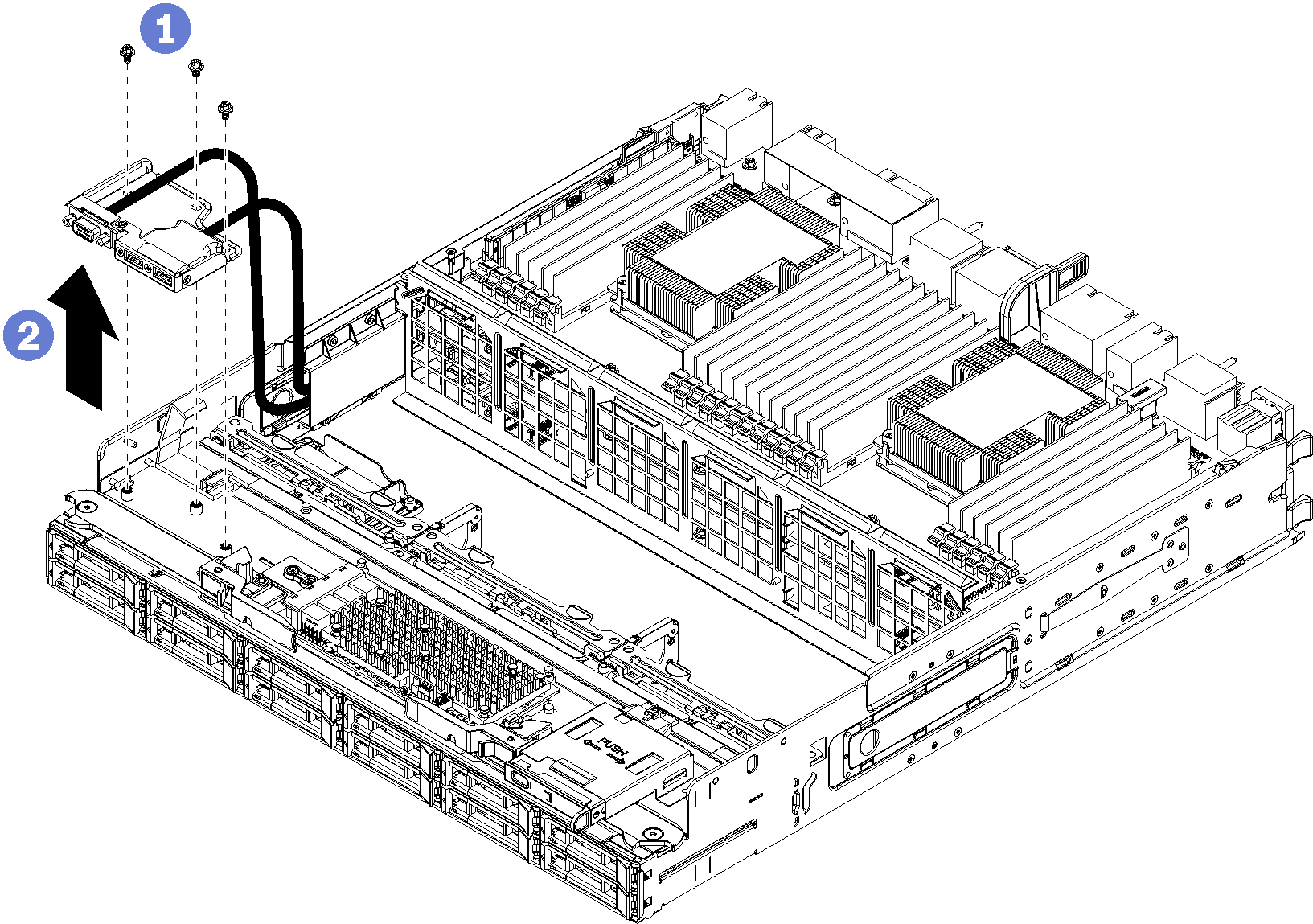
- Disconnect the front USB/VGA assembly cables from the lower system board and unroute the cables. See Cable routing for common components.
- Remove the three screws on the top of the front USB/VGA assembly.
- Remove the front USB/VGA assembly from the compute tray.
If you are instructed to return the front USB/VGA assembly, follow all packaging instructions, and use any packaging materials for shipping that are supplied to you.
Demo video