Install the front USB/VGA assembly
The front USB/VGA assembly is in the lower compute tray that is accessed from the front of the server. Position the front USB/VGA assembly in the lower compute tray and secure with two screws; then, route the front USB/VGA assembly cables to the lower compute system board and connect.


Complete the following steps to install the front USB/VGA assembly.
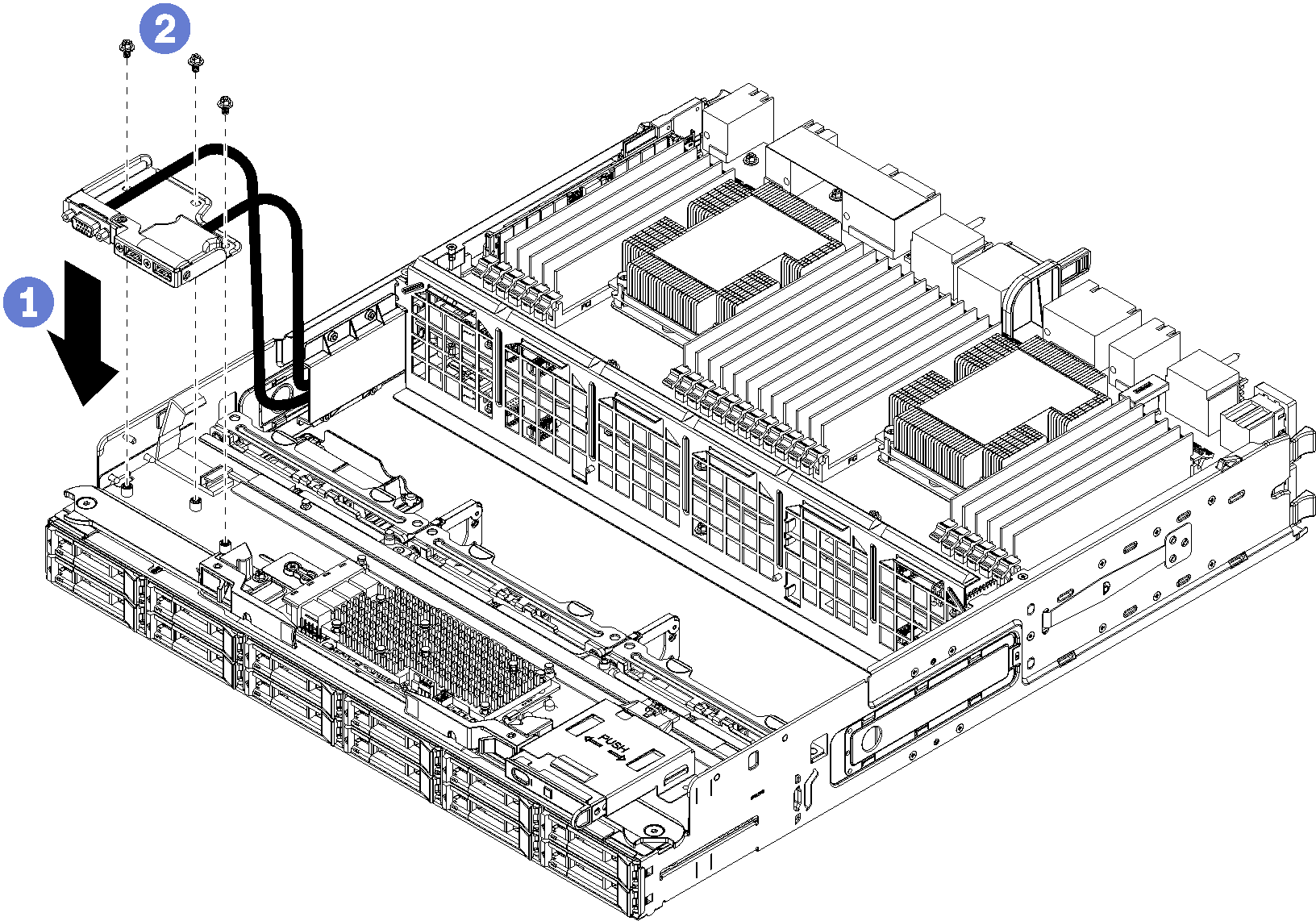
- Position the front USB/VGA assembly in the lower compute tray.
- Install and tighten the three screws on the top of the front USB/VGA assembly.
- Route the front USB/VGA assembly cables to their connectors on the lower system board and connect them. See Cable routing for common components.
After you have installed the front USB/VGA assembly:
Make sure that all cables are correctly routed. See Cable routing for common components and Cable routing for drives.
Install the lower fan cage. See Install a fan cage (lower tray).
If you removed an upper system board or system board filler, install it. See Install a system board.
Install the compute tray; then, install the front cover. See Install a compute tray and Install the front cover.
Demo video