
Install a fan module

Follow the instructions in this section to install a fan module.

About this task

S017
moving parts
CAUTION
Hazardous moving fan blades nearby. Keep fingers and other body parts away.
S033
240VA shock hazard
CAUTION

Hazardous energy present. Voltages with hazardous energy might cause heating when shorted with metal, which might result in spattered metal, burns, or both.

Attention
  • Read Installation Guidelines and Safety inspection checklist to ensure that you work safely.

  • Prevent exposure to static electricity, which might lead to system halt and loss of data, by keeping static-sensitive components in their static-protective packages until installation, and handling these devices with an electrostatic-discharge wrist strap or other grounding system.

Note

Technical rules for system fans

Fans must be installed in a specific order based on the configuration of the server.

ThinkSystem ST650 V3 supports two types of fans:
  • Single rotor 9238 hot-swap fans

  • Dual rotor 9256 hot-swap fans
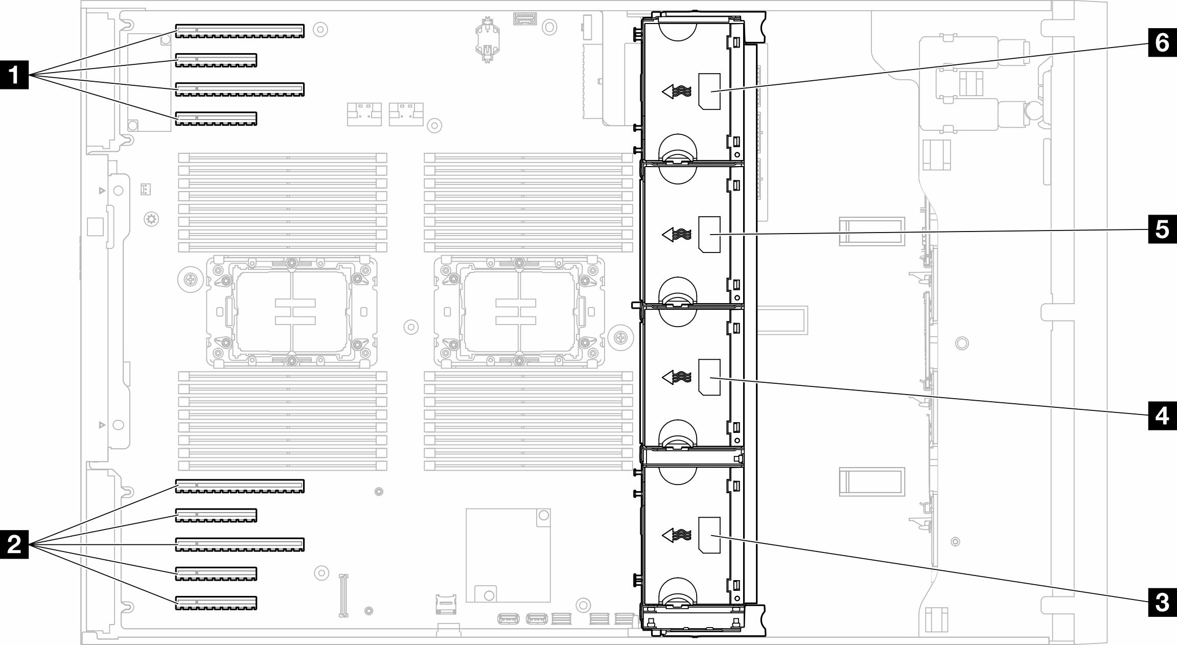
Figure 1. Fan slot locations
Fan slot locations
Table 1. Locations of PCIe slots and fan slots
1 PCIe slot 1-44 Fan slot 2
2 PCIe slot 5-95 Fan slot 3
3 Fan slot 16 Fan slot 4
Note
  • Single-rotor hot-swap fans cannot be mixed with dual-rotor hot-swap fans.

  • When the system is powered off but still plugged in to AC power, the fan in slot 4 may continue to spin at a much lower speed. This is the system design to provide proper cooling.

Back to top

One processor

When only one processor is installed, PCIe slots 1 to 4 and 9 are supported. For more details about the rules of PCIe slots with one processor, see PCIe installation rules with one processor.

For more details about PCIe installation rules with one processor, see PCIe installation rules with one processor.

Table 2. Fan configuration with one processor
Fan configurationDescription
  • Three single rotor fans in fan slots 1, 2, and 4.

  • One fan filler in fan slot 3.

  1. Supports one CPU with TDP less than 200 watts.

  2. Supports RDIMMs with capacity smaller than 64 GB.

  3. GPU adapters are not supported.

  4. Supports up to sixteen 2.5-inch SAS/SATA drives (two 2.5-inch SAS/SATA drive backplanes).

  5. Supports up to eight 3.5-inch SAS/SATA drives (two 3.5-in SAS/SATA backplanes).

  6. Fan redundancy is not supported.

  • Three dual rotor fans in fan slots 1, 2, and 4.

  • One fan filler in fan slot 3.

  1. All CPU SKUs are supported.

  2. Supports RDIMMs with capacity smaller than 128 GB.

  3. Supports either of the following GPU adapters:

    • up to four single-width GPUs of the same type.

    • up to two double-width GPUs of the same type.

  4. Supports up to sixteen 2.5-inch SAS/SATA drives (two 2.5-inch SAS/SATA drive backplanes).

  5. Supports up to eight 3.5-inch SAS/SATA drives (two 3.5-in SAS/SATA backplanes).

  6. Supports ThinkSystem M.2 SATA/NVMe 2-Bay Enablement Kit.

  7. Supports ThinkSystem M.2 NVMe 2-Bay RAID Enablement Kit

  8. Supports fan redundancy.

Four single rotor fans in fan slots 1, 2, 3, and 4.

  1. Supports one CPU with TDP less than 200 watts.

  2. Supports RDIMMs with capacity smaller than 64 GB.

  3. GPU adapters are not supported.

  4. Supports up to thirty-two 2.5-inch SAS/SATA drives (four 2.5-inch SAS/SATA drive backplanes).

  5. Supports up to sixteen 3.5-inch SAS/SATA drives (four 3.5-inch SAS/SATA drive backplanes).

  6. Fan redundancy is not supported.

  • Four dual rotor fans in fan slots 1, 2, 3, and 4.

  • All CPU SKUs

  • RDIMMs with capacity smaller than 64 GB

  1. GPU adapters are not supported.

  2. Supports up to thirty-two 2.5-inch SAS/SATA/NVMe drives (four 2.5-inch SAS/SATA or Anybay drive backplanes).

  3. Supports up to sixteen 3.5-inch SAS/SATA/NVMe drives (four 3.5-inch SAS/SATA or Anybay drive backplanes)

  4. Supports ThinkSystem M.2 SATA/NVMe 2-Bay Enablement Kit.

  5. Supports ThinkSystem M.2 NVMe 2-Bay RAID Enablement Kit

  6. Supports fan redundancy.

  • Four dual rotor fans in fan slots 1, 2, 3, and 4.

  • All CPU SKUs

  • RDIMMs with capacity smaller than 128 GB

  1. Supports either of the following GPU adapters:

    • up to four single-width GPUs of the same type.

    • up to two double-width GPUs of the same type.

  2. Supports up to sixteen 2.5-inch SAS/SATA/NVMe drives (two 2.5-inch SAS/SATA or Anybay drive backplanes).

  3. Supports up to eight 3.5-inch SAS/SATA/NVMe drives (two 3.5-inch SAS/SATA or Anybay drive backplanes).

  4. Supports ThinkSystem M.2 SATA/NVMe 2-Bay Enablement Kit.

  5. Supports ThinkSystem M.2 NVMe 2-Bay RAID Enablement Kit

  6. Supports fan redundancy.

  • Four dual rotor fans in fan slots 1, 2, 3, and 4.

  • CPU with TDP less than 200 watts

  • RDIMMs with capacity smaller than 64 GB

  1. Supports up to four A2 or L4 GPUs.

  2. Supports up to thirty-two 2.5-inch SAS/SATA/NVMe drives (four 2.5-inch SAS/SATA or Anybay drive backplanes).

  3. Supports up to sixteen 3.5-inch SAS/SATA/NVMe drives (four 3.5-inch SAS/SATA or Anybay drive backplanes).

  4. Supports ThinkSystem M.2 SATA/NVMe 2-Bay Enablement Kit.

  5. Supports ThinkSystem M.2 NVMe 2-Bay RAID Enablement Kit

  6. Supports fan redundancy.

Back to top

Two processors

For more details about PCIe installation rules with two processors, see PCIe installation rules with two processors.

Table 3. Fan configuration with two processors
Fan configurationDescription

Four single rotor fans in fan slot 1, 2, 3, and 4.

  1. Supports two CPUs with TDP less than 200 watts.

  2. Supports RDIMMs with capacity smaller than 64 GB.

  3. GPU adapters are not supported.

  4. Supports up to thirty-two 2.5-inch SAS/SATA drives (four 2.5-inch SAS/SATA drive backplanes).

  5. Supports up to sixteen 3.5-inch SAS/SATA drives (four 3.5-inch SAS/SATA drive backplanes).

  6. Fan redundancy is not supported.

    Fan redundancy is not supported.

  • Four dual rotor fans in fan slots 1, 2, 3, and 4.

  • RDIMMs with capacity smaller than 64 GB

  • Two CPUs with TDP less than 200 watts

  1. Supports up to eight A2 or L4 GPUs.

  2. Supports up to thirty-two 2.5-inch SAS/SATA/NVMe drives (four 2.5-inch SAS/SATA or Anybay drive backplanes).

  3. Supports up to sixteen 3.5-inch SAS/SATA/NVMe drives (four 3.5-inch SAS/SATA or Anybay drive backplanes).

  4. Supports ThinkSystem M.2 SATA/NVMe 2-Bay Enablement Kit.

  5. Supports ThinkSystem M.2 NVMe 2-Bay RAID Enablement Kit

  6. Supports fan redundancy.

  • Four dual rotor fans in fan slots 1, 2, 3, and 4.

  • All CPU SKUs for the two CPUs

  • RDIMMs with capacity smaller than 128 GB

  1. Supports GPU adapters listed below:

    • up to eight single-width GPUs.

    • up to four double-width GPUs.

    • up to four single-width GPUs and two double-width GPUs.

    • ThinkSystem ST650 V3 does not support mixing GPUs between PCIe slots 1 and 4 or between slots 5 and 8.
      • When a GPU is installed between PCIe slots 1 and 4, only the same type of GPUs can be installed in other slots between 1 and 4.

      • When a GPU is installed between PCIe slots 5 and 8, only the same type of GPUs can be installed in other slots between 5 and 8.

    • See GPU installation rules for more details of the technical rules for GPU installation.

  2. Supports up to sixteen 2.5-inch SAS/SATA/NVMe drives (two 2.5-inch SAS/SATA or Anybay drive backplanes).

  3. Supports up to eight 3.5-inch SAS/SATA/NVMe drives (two 3.5-inch SAS/SATA or Anybay drive backplanes).

  4. Supports ThinkSystem M.2 SATA/NVMe 2-Bay Enablement Kit.

  5. Supports ThinkSystem M.2 NVMe 2-Bay RAID Enablement Kit

  6. Supports fan redundancy.

Back to top

Installation Procedure

Follow the instructions in this section to install a fan module.

Note

Depending on the specific configuration, the component might look different from the illustrations in this section.
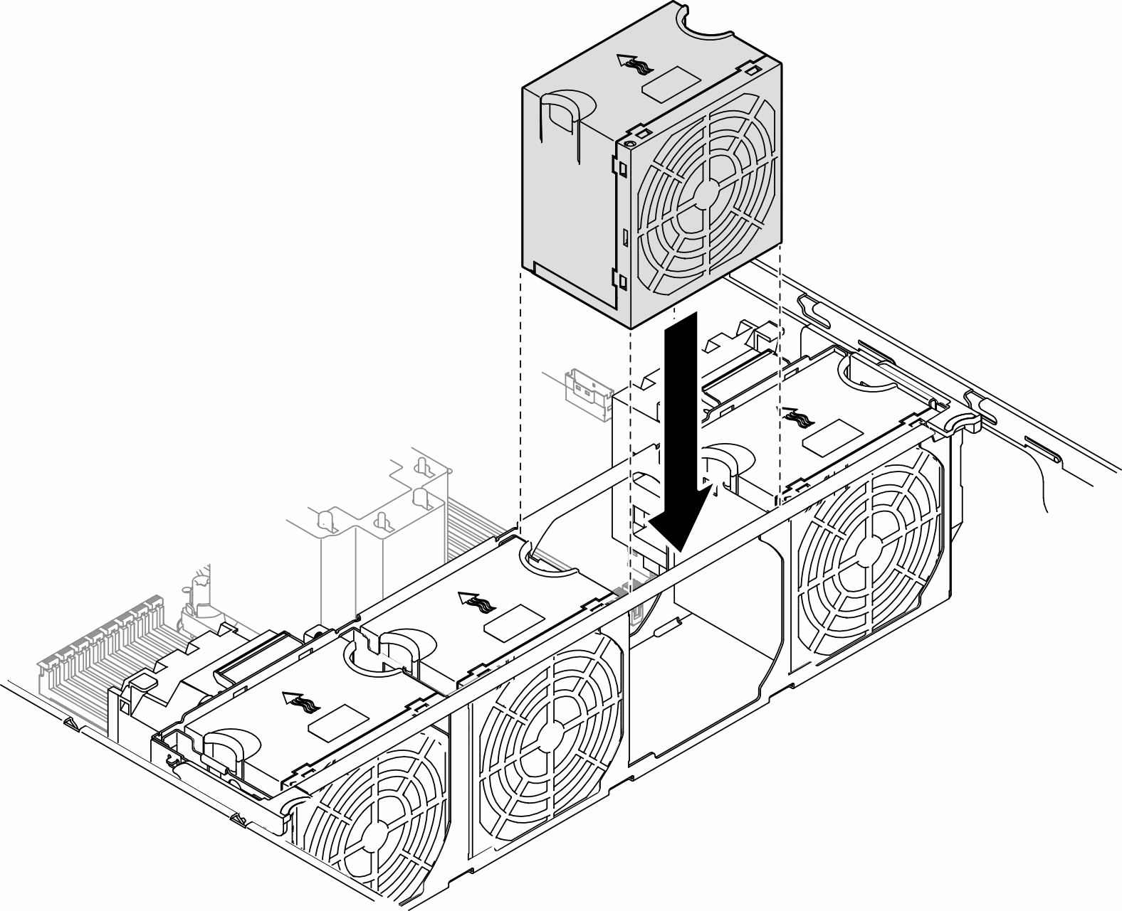
Procedure

  1. Locate the slot in the fan cage to install the fan module.
  2. Align the fan module over the fan slot in the fan cage.
  3. Push the fan module into the fan cage until it snaps into position .
    Figure 2. Installation of a fan module
    Fan module installation

After this task is completed

  1. Reinstall the server cover. See Install a server cover.

  2. Complete the parts replacement. See Complete the parts replacement.

Back to top