Installing the optional ServeRAID M5120 SAS/SATA Controller
Use this information to install the optional ServeRAID M5120 SAS/SATA Controller.
You can purchase an optional ServeRAID M5120 SAS/SATA Controller. This adapter can be installed only in the PCIe slots listed in Supported adapters. For configuration information, see the ServeRAID documentation at Lenovo Data Center Support.
Attention
Some cluster solutions require specific code levels or coordinated code updates. If the device is part of a cluster solution, verify that the latest level of code is supported for the cluster solution before you update the code.
Note
- For additional information and notes about installing adapters Installing an adapter.
- Follow the general rule for connecting the SAS signal cables to the adapter and drive backplane: port 0 on the adapter to port 0 on the drive backplane and port 1 on the adapter to port 1 on the drive backplane (depending on the type of drive backplane you install in the server).
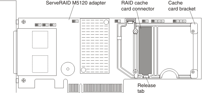
- This adapter comes with a RAID cache card. The cache card comes with a battery or flash power module that must be installed remotely in the server (see Installing a RAID adapter flash power module for more information).
- This adapter is for external RAID and can be used when external storage expansion units are attached to the server.
To install the ServeRAID M5120 SAS/SATA adapter, complete the following steps:
Note
If possible, backup or record your RAID configuration information before replacing the adapter. See the documentation for your RAID adapter for information and instructions. Documentation for ServeRAID adapters can be downloaded from the Lenovo Support Portal.
- Read the safety information and installation guidelines, see Safety and Installation guidelines.
- Turn off the server (see Turning off the server) and all attached peripheral devices. Disconnect all power cords; then, disconnect all external cables from the server.
- Remove the top cover (see Removing the server top cover).
- Remove the fan cage assembly (see Removing the fan cage assembly).
- Remove the microprocessor and memory expansion tray (see Removing the microprocessor and memory expansion tray assembly) or DIMM air baffle (see Removing the DIMM air baffle), whichever one is installed.
- Touch the static-protective package that contains the adapter to any unpainted surface on the outside of the server; then, grasp the adapter by the top edge or upper corners of the adapter and remove it from the package.
- If the RAID cache card is not already attached to the adapter, see Installing a RAID cache card and Installing a RAID adapter flash power module for instructions on installing and cabling the cache card.
- Use one of the following procedures:
If you have other devices to install or remove, do so now. Otherwise, go to Completing the installation.
Give documentation feedback