Remove a Power Conversion Station (PCS)
Use this information to remove a Power Conversion Station (PCS).
About this task
Lift tool assembly
Genie GL-8 lift tool installed with the lift tool fixture. The foot-release brake should also be attached to the lift tool.
For assembling instructions, see Setting up the lift tool assembly
For mandatory tools ordering information, see ThinkSystem server options.

To avoid a shock hazard:
- Connect all power cords to a properly wired and grounded electrical outlet/source.
- Connect any equipment that will be attached to this product to properly wired outlets/sources.
- When possible, use one hand only to connect or disconnect signal cables.
- Never turn on any equipment when there is evidence of fire, water, or structural damage.
- The device might have more than one power cord, to remove all electrical current from the device, ensure that all power cords are disconnected from the power source.


Never remove the cover on a power supply or any part that has this label attached. Hazardous voltage, current, and energy levels are present inside any component that has this label attached. There are no serviceable parts inside these components. If you suspect a problem with one of these parts, contact a service technician.

High touch current. Connect to earth before connecting to supply.
Read Installation Guidelines and Safety inspection checklist to ensure that you work safely.
Disconnect the power cord from the connector on the back of the power conversion station.
If only one PCS is installed in the solution, you must turn off the solution before removing the power conversion station.
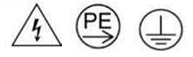
In some configurations, the PCS are connected to a Y-splitter power cord. In such cases, the Y-splitter cord is connected to a rack power cord that is connected to the facility power outlet. It is NOT allowed to disconnect the Y-splitter power cord and the rack power cord.
Figure 2. Disconnection NOT allowed between Y-splitter power cord and rack power cord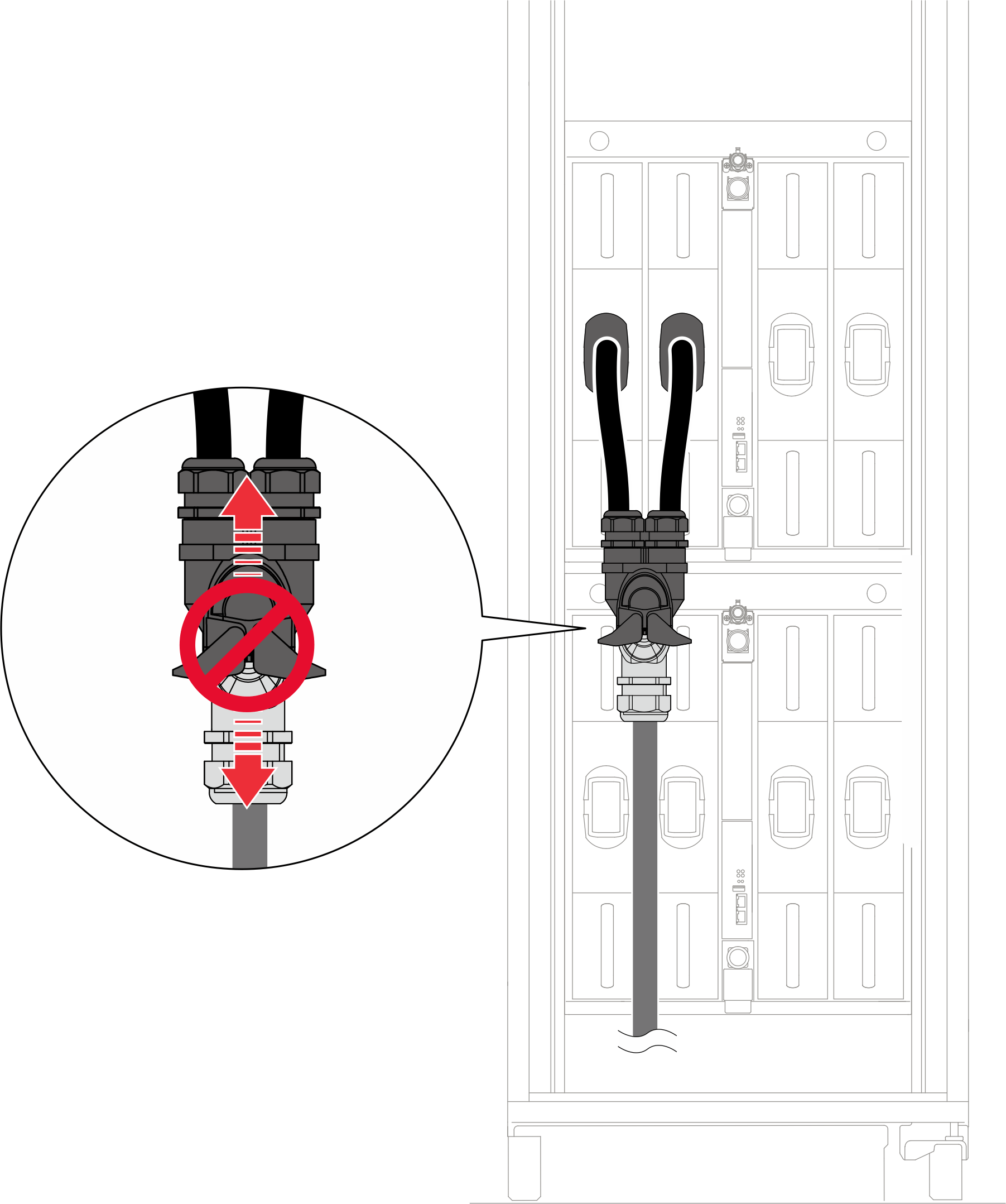
Before removing the PCS, it is strongly suggested to reduce the power loading of each node installed in the enclosure by turning the node into idle state or power off state.
When removing the PCS, the following SMM3 event messages may appear. These SMM3 event messages can be ignored before a replacement PCS is installed. For more information, see Messages.
| SMM3 messages | Affected PCS | Description |
|---|---|---|
| These events were asserted due to insufficient power bank, and can be ignored. | ||
| 1807010015 | N/A | FPGA Throttle: Chassis, transition to Non-Critical from OK was asserted |
| 180702001A | Encl PMax Exceed: Chassis, transition to Critical from less severe was asserted | |
| 180702001B | Encl PMin Exceed: Chassis, transition to Critical from less severe was asserted | |
| On PCS removed from the chassis, these events can be treated as normal. | ||
| 0807070048 / 0807070049 / 080707004A / 080707004B | PCS 1 / PCS 2 / PCS 3 / PCS 4 | PCS # EPOW: Power Supply sensor, Monitor was asserted |
| 086F030040 / 086F030041 / 086F030042 / 086F030043 | PCS #: Power Supply sensor, Power Supply input lost (AC/DC) was asserted | |
| 086F010050 / 086F010051 / 086F010052 / 086F010053 | PCS # Vin UV: Power Supply sensor, Power Supply Failure detected was asserted | |
| 090B030011 | N/A | Power Resource: Power Unit sensor, Non-redundant: Sufficient from Redundant was asserted |
| 0887070048 / 0887070049 / 088707004A / 088707004B | PCS 1 / PCS 2 / PCS 3 / PCS 4 | PCS # EPOW: Power Supply sensor, Monitor was deasserted |
| 08EF000040 / 08EF000041 / 08EF000042 / 08EF000043 | PCS #: Presence detected was deasserted | |
| 08EF030040 / 08EF030041 / 08EF030042 / 08EF030043 | PCS #: Power Supply sensor, Power Supply input lost (AC/DC) was deasserted | |
| 08EF010050 / 08EF010051 / 08EF010052 / 08EF010053 | PCS # Vin UV: Power Supply sensor, Power Supply Failure detected was deasserted | |
| On PCS which stays in the chassis, these events might happen depending on the system loading. | ||
| 080701004C / 080701004D / 080701004E / 080701004F | PCS 1 / PCS 2 / PCS 3 / PCS 4 | PCS 1 / PCS 2 / PCS 3 / PCS 4 : PCS # Throttle : Power Supply, transition to Non-Critical from OK was asserted |
| 086F010054 / 086F010055 / 086F010056 / 086F010057 | PCS 1 / PCS 2 / PCS 3 / PCS 4 : PCS # Iout OC : Power Supply, Failure detected was asserted | |
| 086F010060 / 086F010061 / 086F010062 / 086F010063 | PCS 1 / PCS 2 / PCS 3 / PCS 4 : PCS # OverTemp : Power Supply, Failure detected was asserted | |
| 086F010044 / 086F010045 / 086F010046 / 086F010047 | PCS 1 / PCS 2 / PCS 3 / PCS 4 : PCS # OVS Fault : Power Supply, Failure Detected was asserted | |
- A video of this procedure is available at YouTube.
Procedure
- Disconnect the power cable.
 Rotate the power socket latches outwards.
 Disconnect the power cable from the PCS.
Figure 3. Disconnecting the PCS power cable
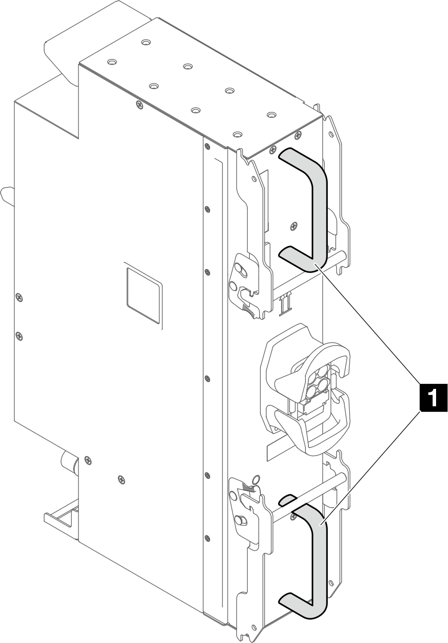
- Remove the PCS slightly out of the enclosure.
- Rotate the latches outwards, the PCS will move slightly out of the enclosure.
- Grab the handles and pull the PCS slightly out of the enclosure.NoteAvoid pulling the PCS too far our and letting the PCS tilt downwards.
 Rotate the latches inwards to the closed position.Figure 4. Pulling the PCS slightly out of the enclosure
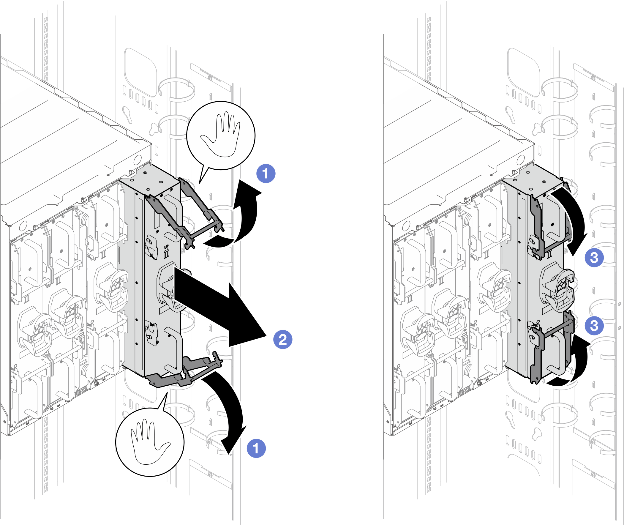
- Adjust the fixture guide fence to the PCS position. If the guide fence is not in the PCS position, lift the guide fence, and re-install it to the PCS slots.
Fence label description Full description SW Single Wide PCS Power Conversion Station DW Double Wide Figure 5. Fixture guide fence set to PCS position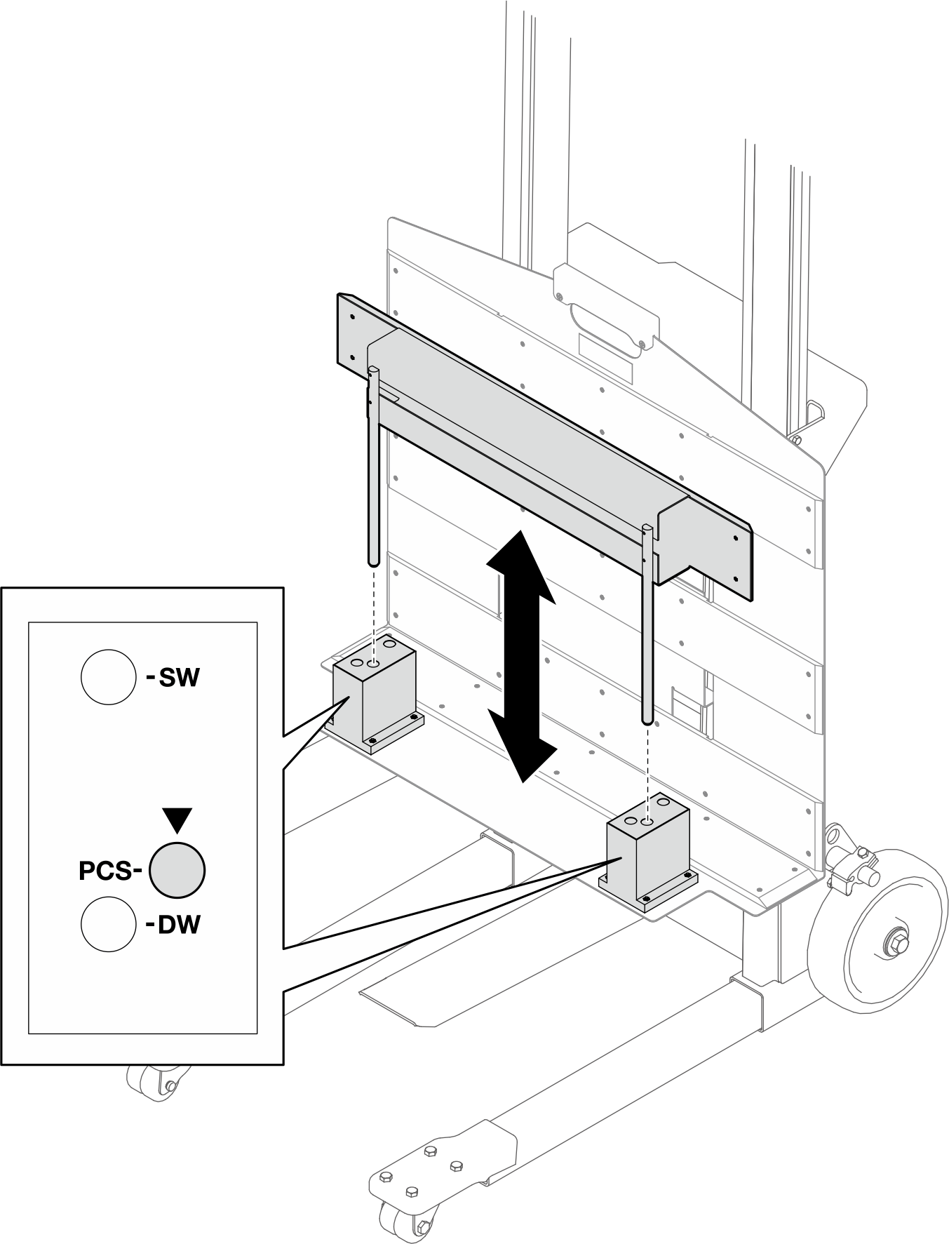
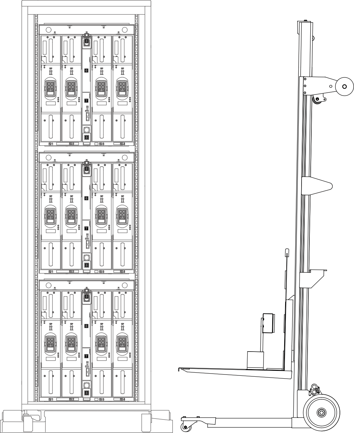
- Move the lift tool assembly to the rear of the rack.Figure 6. Lift tool assembly placement in rear of the rack
- Adjust the lift tool so that the fixture bottom aligns with the PCS bottom, and the fixture front side is in parallel to PCS front side or back side.NoteRotate the lift tool handle
clockwise to raise the fixture; counterclockwise to lower the fixture. 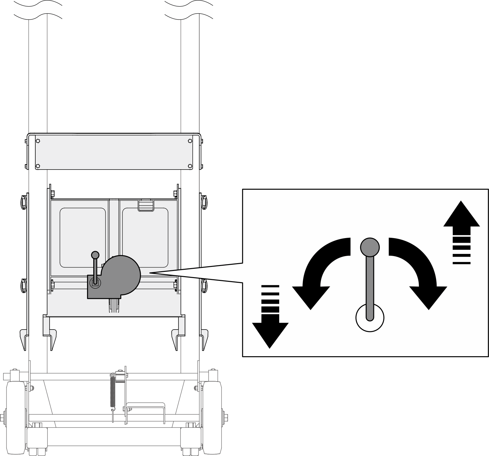 Figure 7. Aligning fixture and the PCS
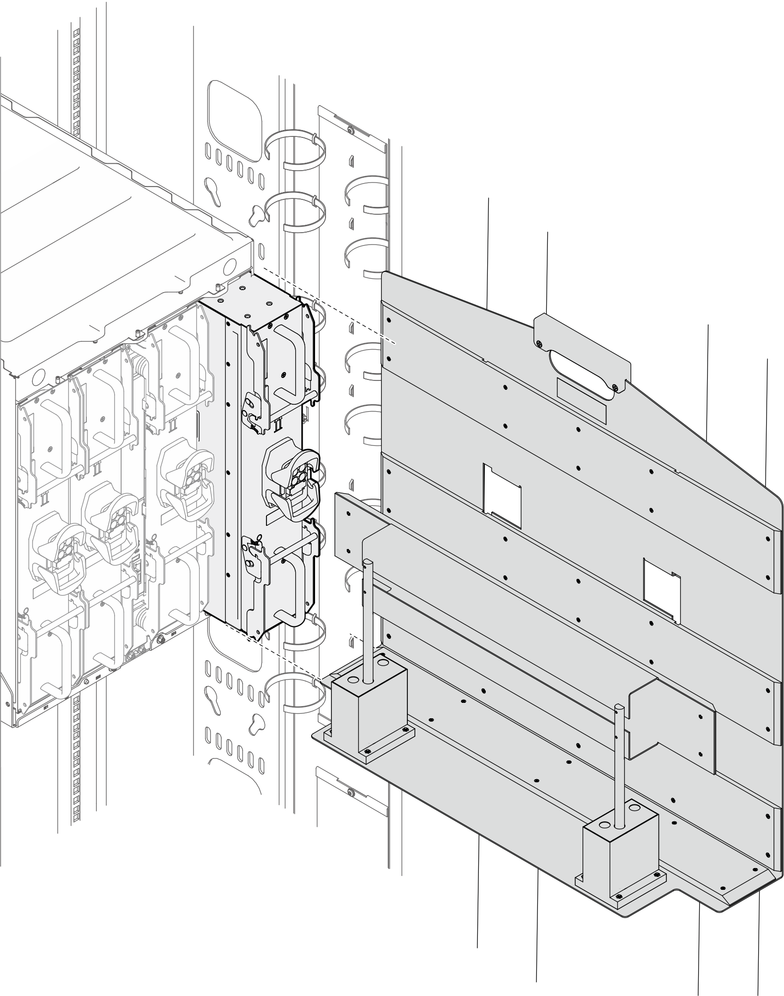
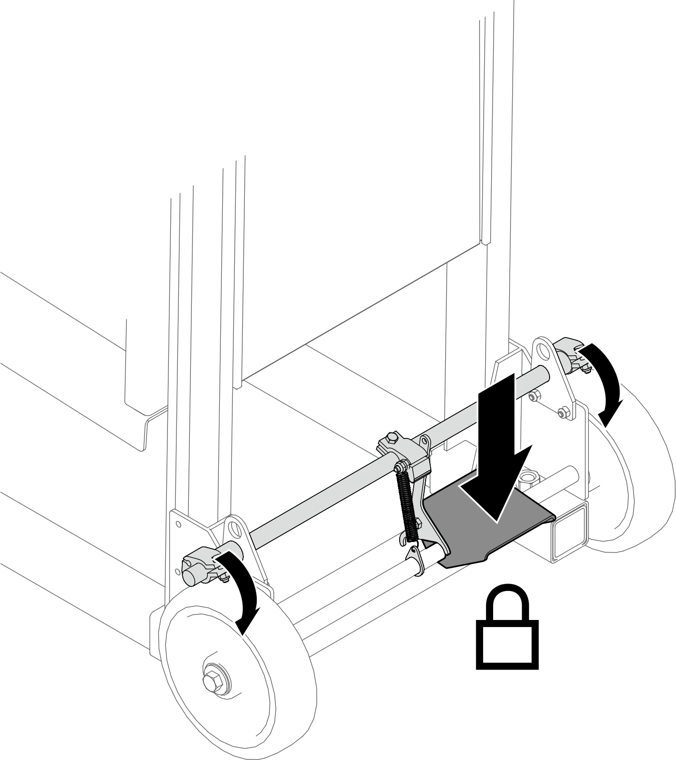
- Push down the foot pedal to lock the wheel brake of the lift tool.Figure 8. Locking the lift tool wheel brake
- Transfer the PCS to the fixture.
- Grab the top and bottom parts of the PCS.
- Push the PCS onto the fixture.
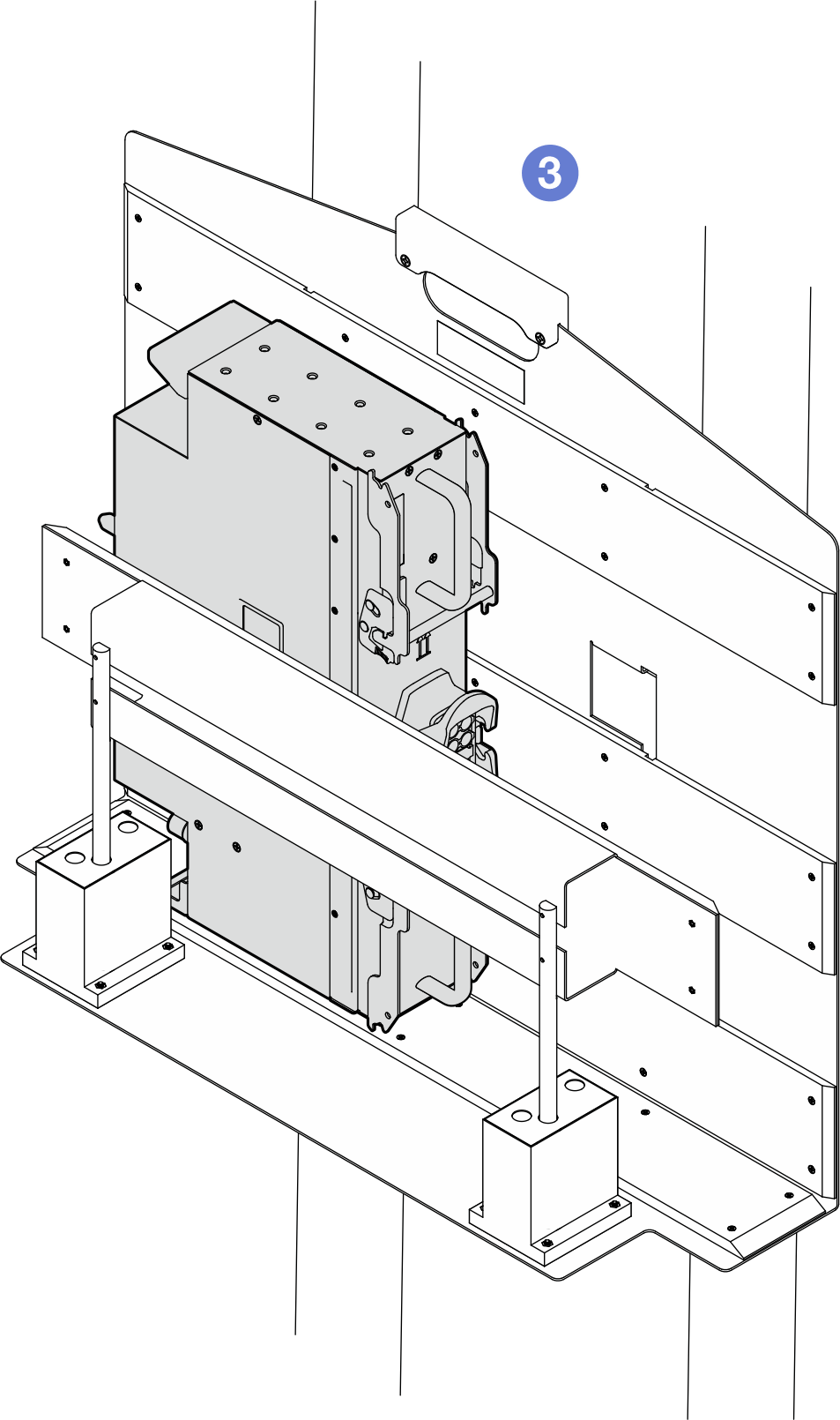
- Make sure the PCS is properly seated in the fixture.
Figure 9. Transferring the tray to the fixture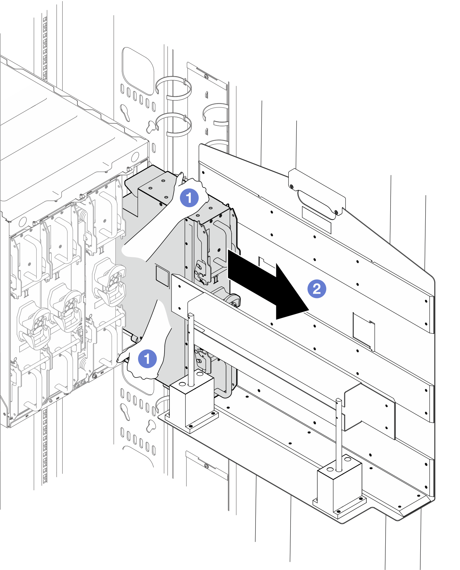
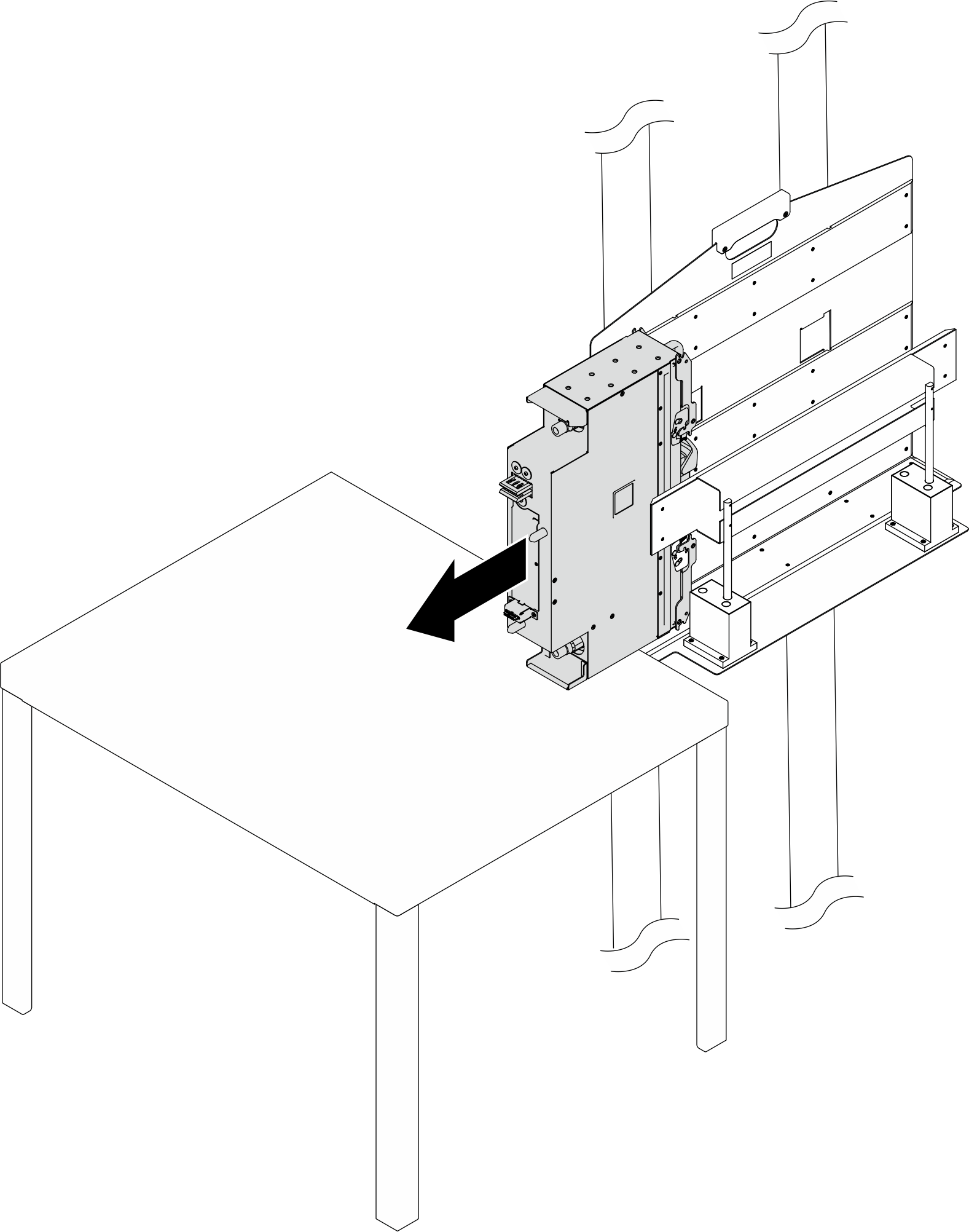
- Transfer the PCS to a work table.Figure 10. Transferring the PCS to a work table
If you are instructed to return the component or optional device, follow all packaging instructions, and use any packaging materials for shipping that are supplied to you.