Install a rear I/O module
Follow instructions in this section to install a rear I/O module.
About this task
To avoid potential danger, make sure to read and follow the safety information.
Attention
Read Installation Guidelines and Safety inspection checklist to make sure that you work safely.
Touch the static-protective package that contains the component to any unpainted metal surface on the node and chassis; then, take the component out of the package and place it on a static-protective surface.
Procedure
- Install the rear I/O module to the node.
 Align the screw holes on the rear I/O module with the screw holes on the bottom of the node; then, lower the rear I/O module and slightly push it toward the rear into place.
 Tighten the three screws as illustrated to secure the rear I/O module.NoteMake sure that the standoffs are securely seated in the holes of the rear I/O module as illustrated.Figure 1. Installation of the rear I/O module
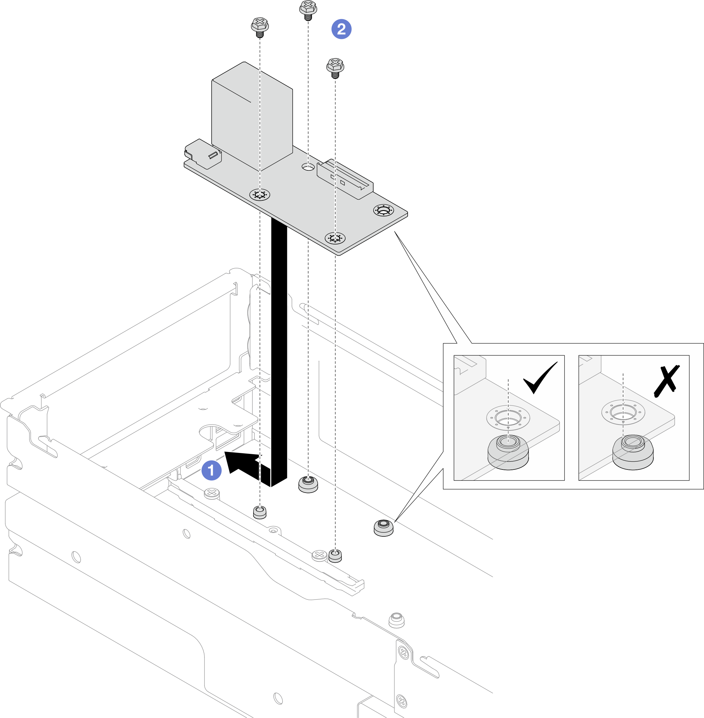
- Reconnect the cables to the rear I/O module.
- Route and connect the cable between the rear I/O module and the system board (see Rear I/O and OCP module cable routing).
- Secure the grounding cable onto the rear I/O module standoff with a screw as illustrated.
Figure 2. Installation of the rear I/O cable and grounding cable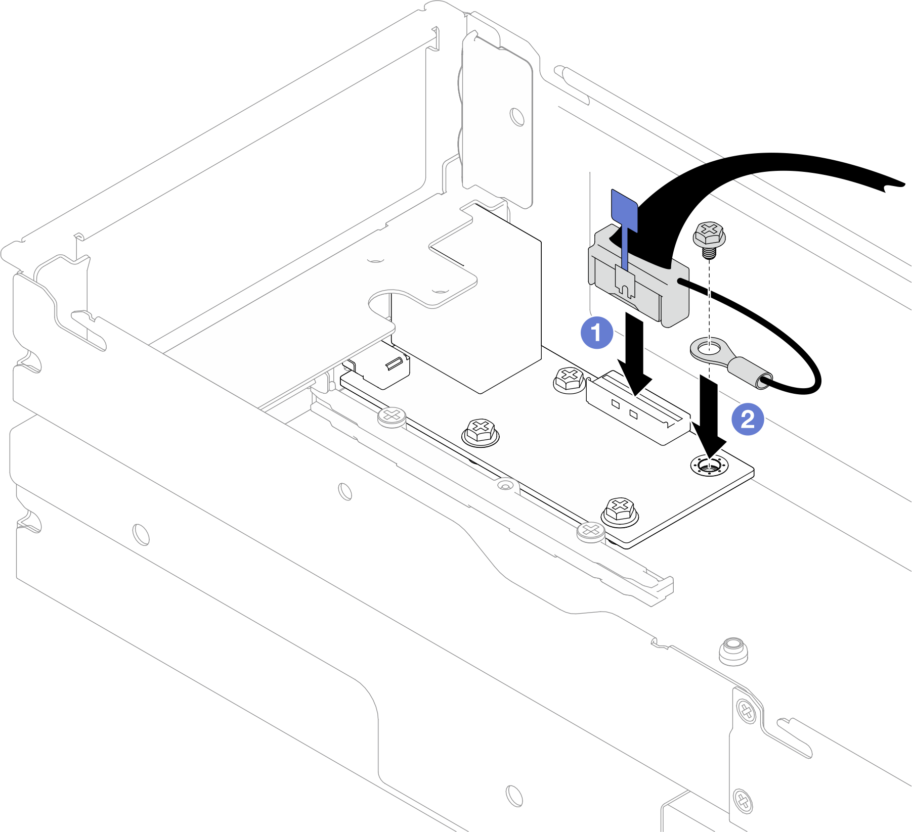
After you finish
- If necessary, reinstall the rear air baffle or 2U performance PHM, front air baffle, and drive cage after reconnecting the rear I/O cable (see Install an air baffle, Install a processor and heat sink, or Install a drive cage assembly).AttentionThe task of removing or installing a 2U performance PHM must be executed by a trained technician.
- If necessary, reinstall the PCIe riser assembly to the node and reconnect the required PCIe cables to the system board (see Install a PCIe riser assembly and PCIe riser cable routing).
- Depending on the specific configuration, reinstall the drive cage, front air baffle, and the rear air baffle or 2U performance PHM, if necessary, after reconnecting the riser cables (see Install a drive cage assembly, Install an air baffle, and Install a processor and heat sink).
- Reinstall the fan cage to the node and reconnect all the fan cables to the system board (see Install a fan cage).
- If necessary, reinstall the GPU air duct (see Install a GPU air duct).
- If necessary, reinstall the internal adapter bracket and reconnect all the required cables to the internal adapter (see Install an internal adapter bracket and 2.5-inch drive backplane cable routing ).
- Make sure that all the required cables are routed and connected correctly; then, reinstall the top cover (see Install the top cover).
- Reinstall the node into the chassis (see Install a node to the chassis).
- Make sure that the required power supply units are installed and power cords are connected; then, power on the node (see Install a hot-swap power supply and Power on the node).
- Proceed to complete the parts replacement (see Complete the parts replacement).
Demo video
Give documentation feedback