Install the water loop
Use this information to install the water loop to the tray.
About this task
Required tools
Make sure you have the required tools listed below in hand to properly replace the component.
Water loop kits
SD650-N V3 Water Loop Gap Pad Kit (The water loop carrier in the Service Kit is reusable, it is recommended to keep it at the facility where the server operates for future replacement needs.)
SD650-N V3 Water Loop Putty Pad Kit
SD650-N V3 SXM5 PCM Fixture
- SXM5 PCM KitNoteContact Lenovo service engineer for guidance on selecting PCM type based on inlet water temperature.
SD650-N V3 OSFP Putty Pad Kit
VR Conduction Plate Parts
Drive gap pad or putty pad kits according to the drives installed in the tray. See their respective replacement procedures for more information.
Screws and screwdrivers
Prepare the following screwdrivers to ensure you can install and remove corresponding screws properly.Screw Type Screwdriver Type Hex screw (GPU node water loop) 6 mm hex head screwdriver Hex screw (OSFP module conduction plate) 4.5 mm hex head screwdriver Torx T10 screw Torx T10 head screwdriver Phillips #1 screw Phillips #1 head screwdriver Phillips #2 screw Phillips #2 head screwdriver
To identify the gap pad/putty pad location and orientation, see Gap pad/Putty pad identification and location.
Before replacing the gap pad/putty pad, gently clean the interface plate or the hardware surface with an alcohol cleaning pad.
Hold the gap pad/putty pad carefully to avoid deformation. Make sure no screw hole or opening is blocked by the gap pad/putty pad material.
Do not use expired putty pad. Check the expiry date on putty pad package. If the putty pads are expired, acquire new ones to properly replace them.
Read Installation Guidelines and Safety inspection checklist to ensure that you work safely.
Turn off the corresponding DWC tray that you are going to perform the task on.
Disconnect all external cables from the enclosure.
Use extra force to disconnect QSFP cables if they are connected to the solution.
To avoid damaging the water loop, always use the water loop carrier when removing, installing or folding the water loop.
A torque screwdriver is available for request if you do not have one at hand.
- A video of this procedure is available at YouTube.
Procedure
- Follow the following steps if you are replacing processors:
- Apply the thermal grease on the top of the processor with syringe by forming four uniformly spaced dots, while each dot consists of about 0.1 ml of thermal greaseNoteCarefully place the processor and retainer on a flat surface with the processor-contact side down.Figure 1. Thermal grease application
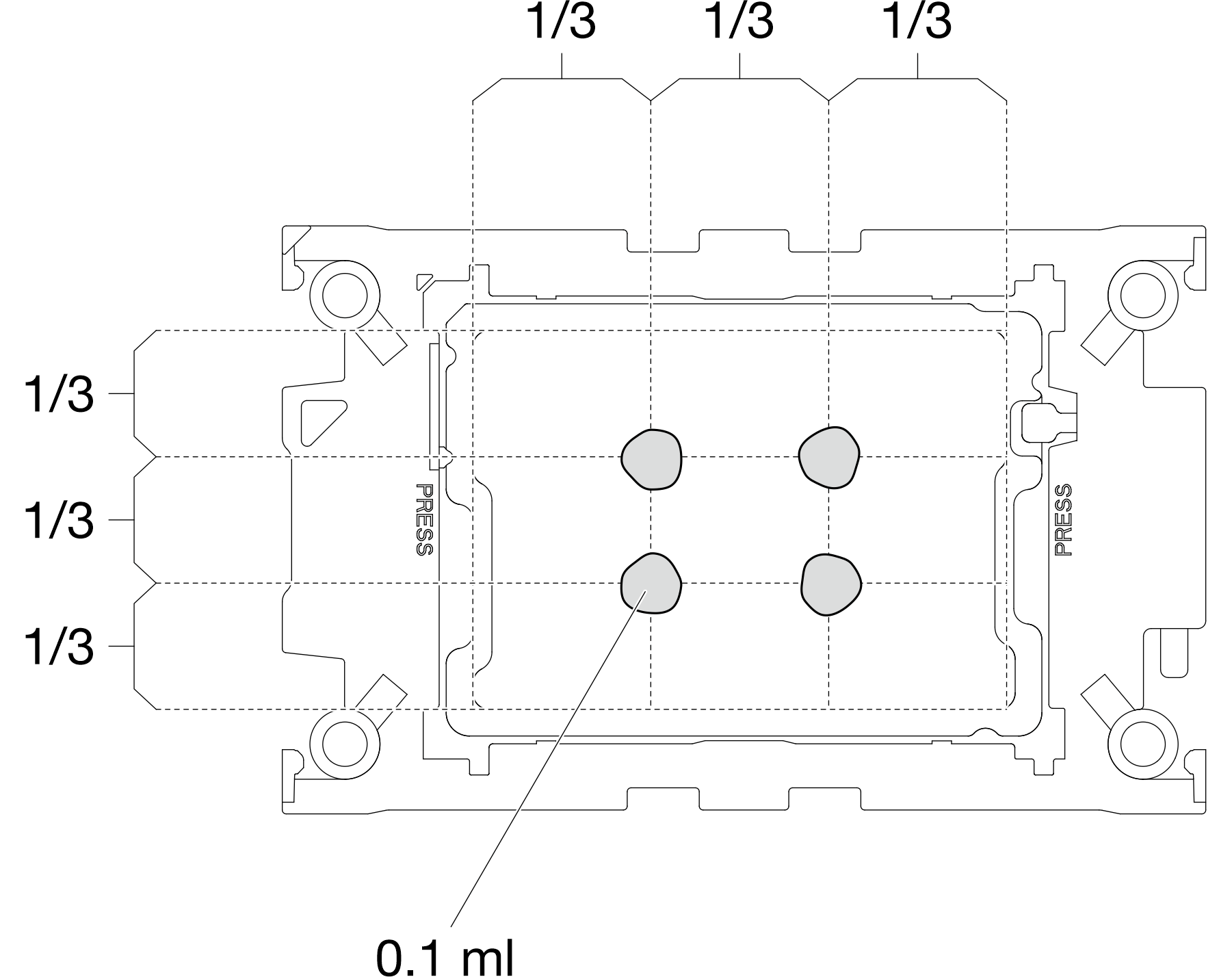
- Apply the thermal grease on the top of the processor with syringe by forming four uniformly spaced dots, while each dot consists of about 0.1 ml of thermal grease
- Install processor retainers onto processor if needed.
- Gently place the processor retainer on the processor; then, carefully press the four sides of the processor retainer to secure the processor.Figure 2. Installing a processor retainer
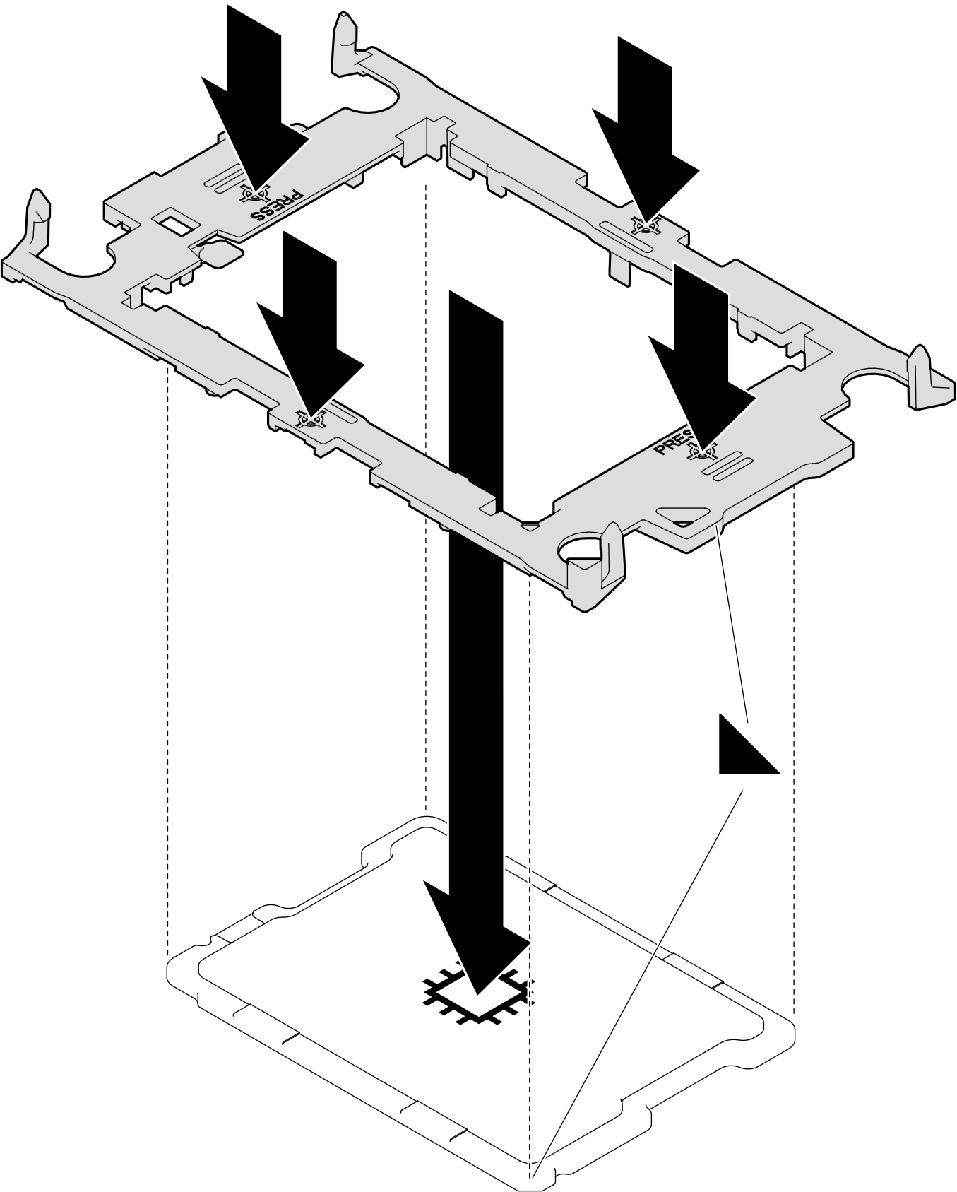 Figure 3. Installing a Intel® Xeon® CPU Max processor retainer
1 TIM breaking cam
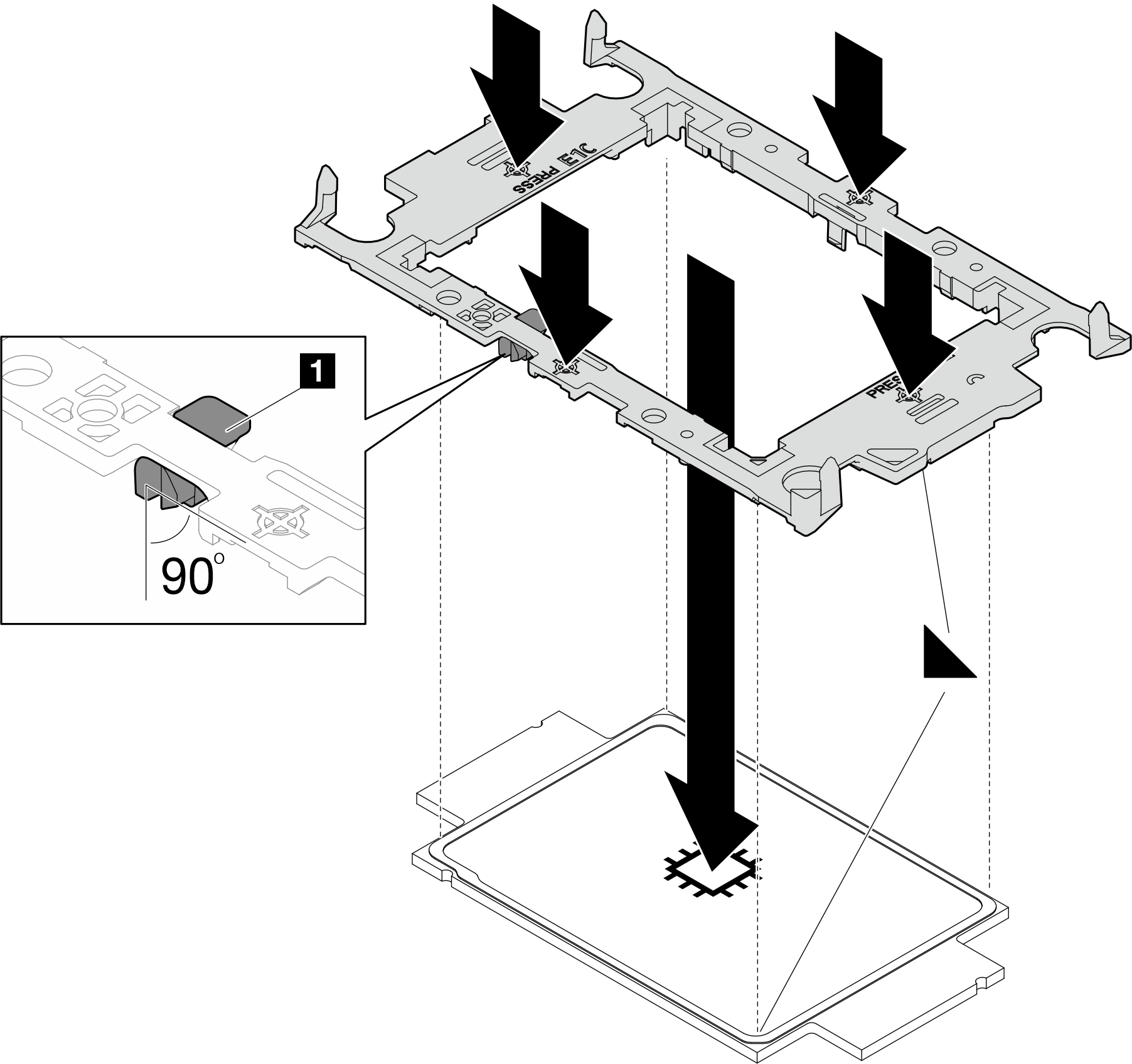
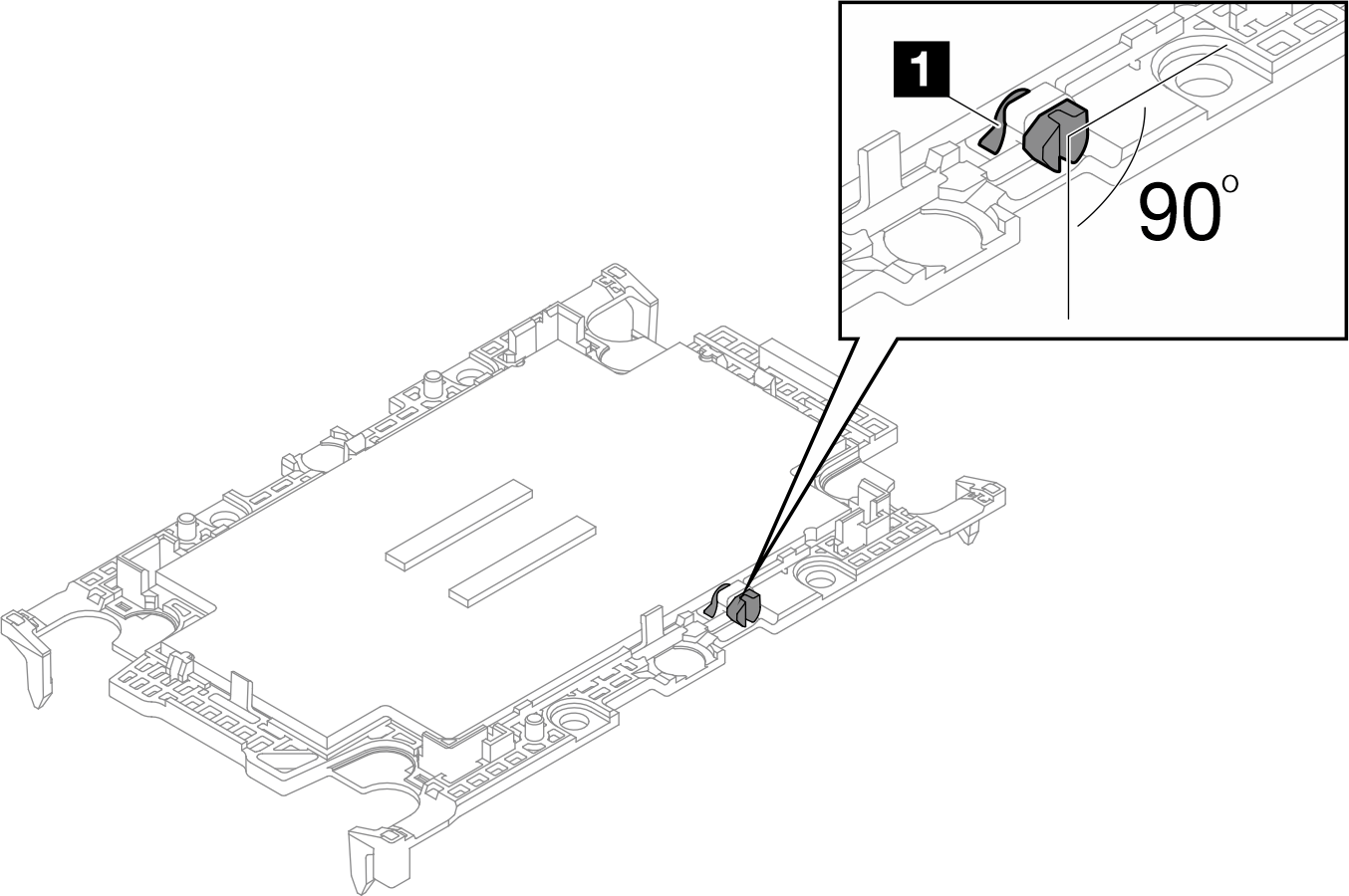
- (Intel® Xeon® CPU Max only) After installing the retainer onto processor, make sure the slot on the TIM breaking cam is vertical.Figure 4. TIM breaking cam on processor retainer
1 TIM breaking cam
- Gently place the processor retainer on the processor; then, carefully press the four sides of the processor retainer to secure the processor.
- When removing the water loop from the package box, make sure to hold the touch points marked in grey in the illustration below.AttentionHolding the water loop anywhere other than the touch points may cause damage to it.Figure 5. Touching points when removing water loop from package box
Top image Isometric view of water loop Bottom image Top view of the water loop 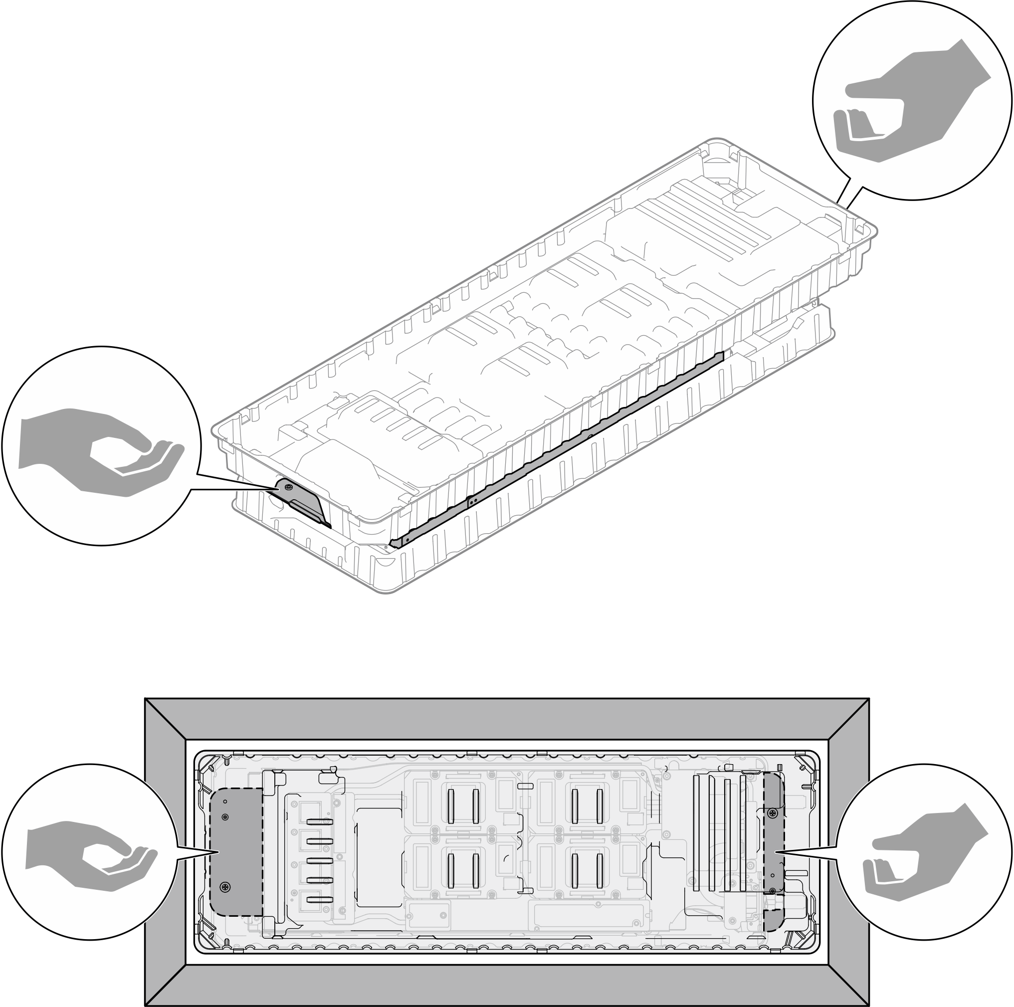
- If needed, remove plastic grease covers from the underside of processor cold plates.Figure 6. Plastic grease covers removal
- Remove two plastic grease covers if needed.
 Use a pair of scissors to cut off the tape.
 Remove plastic grease covers from the underside of water loop cold plates.
NoteThe right node is shown as example. Remove plastic grease covers if needed when installing processor in either node.Figure 7. Plastic grease covers removal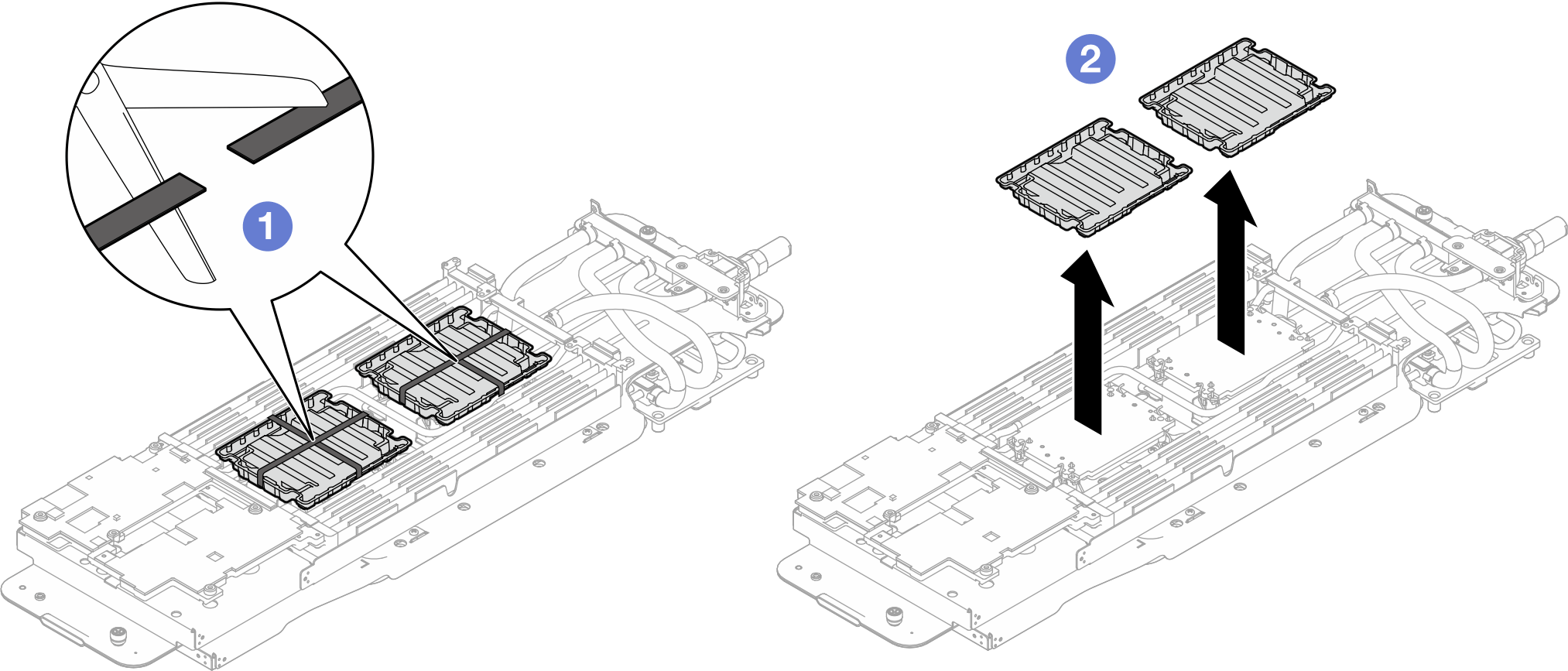
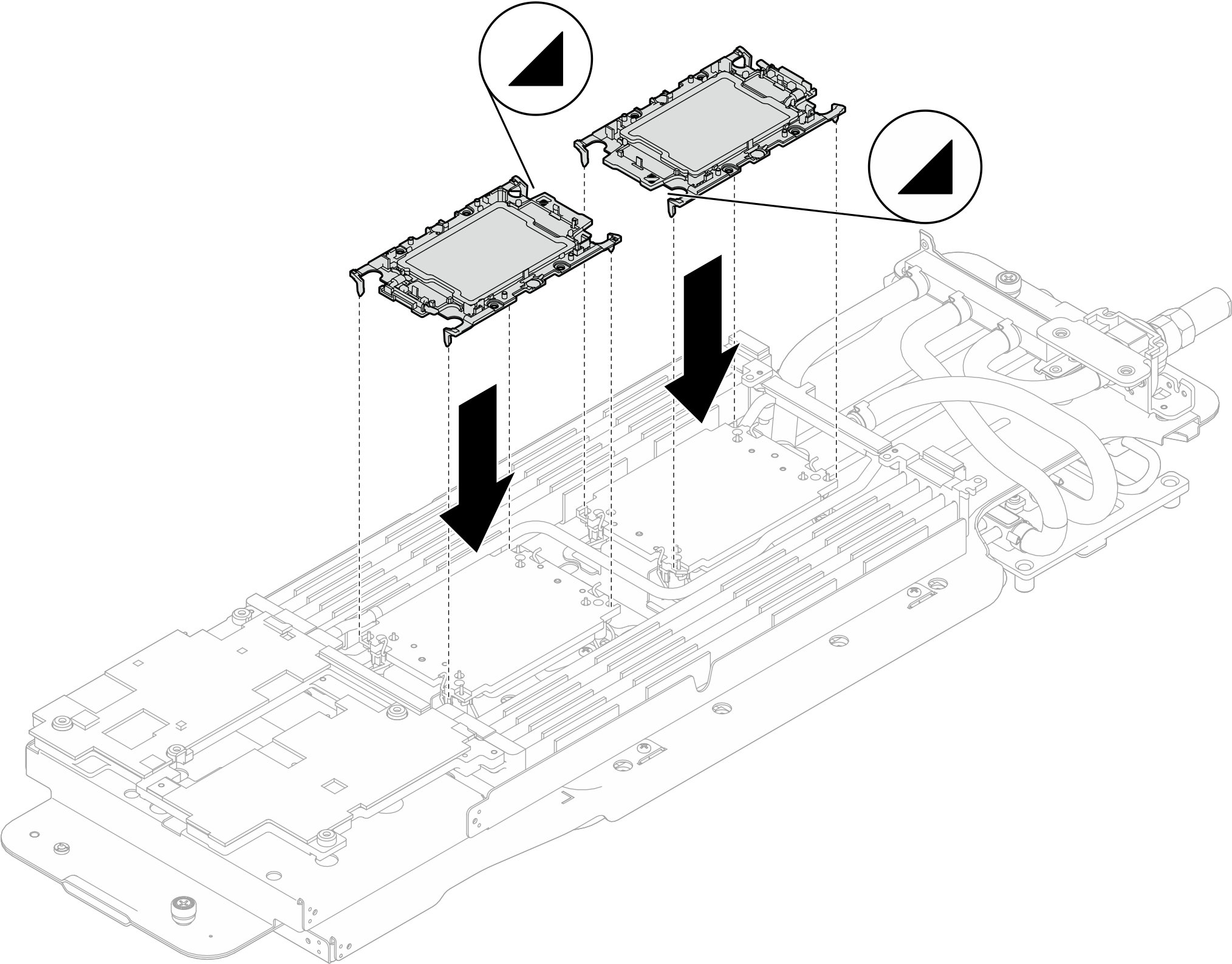
- Align the triangular marks on the processor retainers with the triangular slots on the underside of the water loop cold plate; then, attach the processors to the underside of the water loop cold plate by inserting the processor retainer posts and clips features into the openings at the four corners of the cold plate.Figure 8. Processor installation
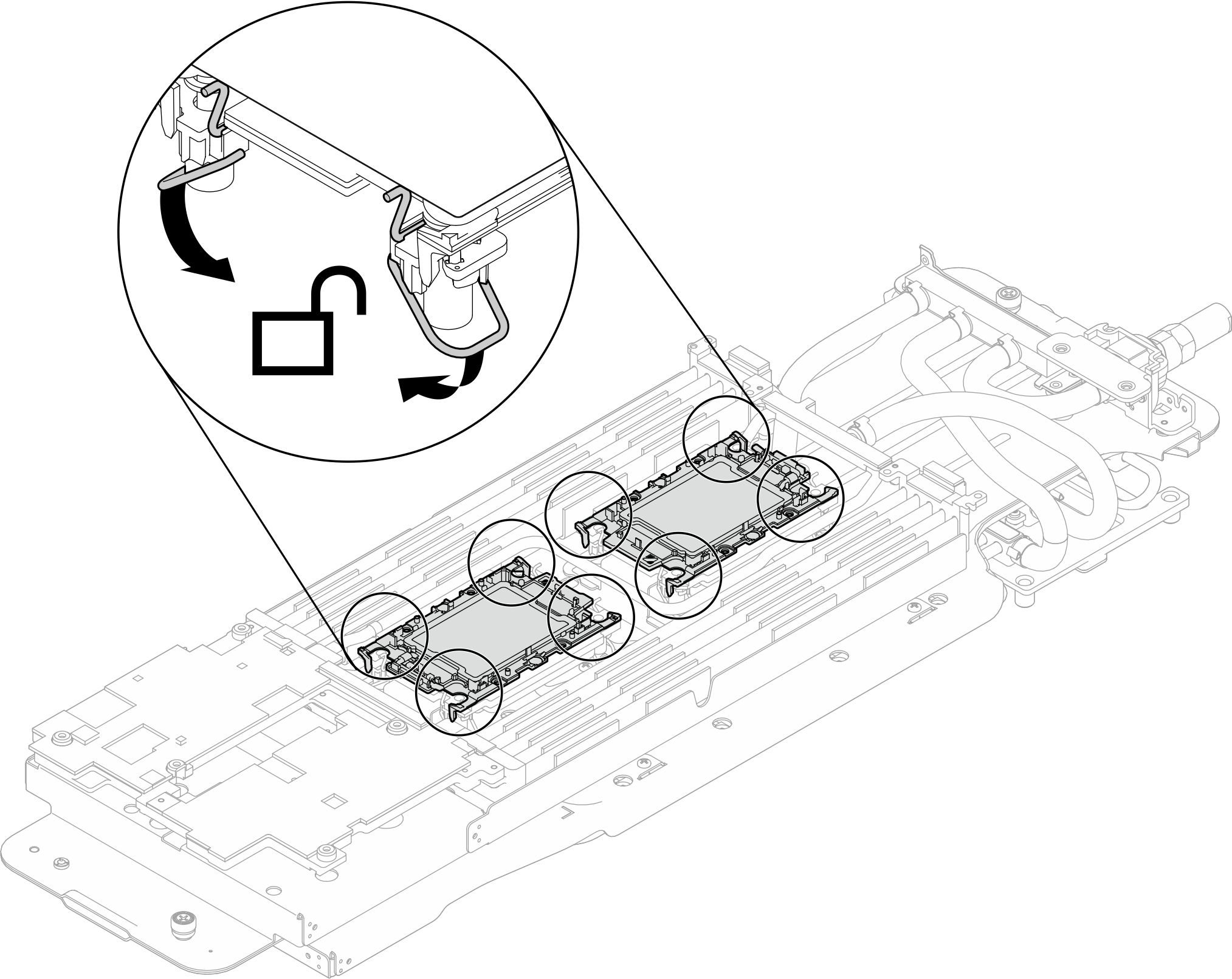
- Rotate all anti-tilt wire bails (8x anti-tilt wire bails per node) outwards to the unlocked position.Figure 9. Processor unlocked position
- Check the gap pads on the water loop, if any of them are damaged or detached, replace them with the new ones.Figure 10. Water loop gap pads
GPU node water loop gap pad/putty pad replacement. Make sure to follow Gap pad/putty pad replacement guidelines.
- Replace the Phase Change Material (PCM) and putty pads on the GPU node water loop with new ones.
- Install the PCM jig on the GPU cold plate.
- Attach the PCM to the square opening of the jig.
- Repeat to replace the PCM of all four GPU cold plates.Attention
PCM cannot be reused. PCM must be replaced with new ones every time the water loop is removed.
After PCM is replaced, there is an expected short duration of throttling before the GPU returns to normal operation. This is due to the PCM requiring a break-in period after being replaced.
After replacing the GPU PCM and putty pads, servicers must perform the H100/H200 GPU PCM TIM melting procedure to monitor the GPU until the PCM Thermal Interface Material (TIM) has melted.
When performing the melting H100/H200 GPU PCM TIM procedures, the minimum water temperature is 35°C (95°F). Do not operate the melting process with water temperature lower than 35°C (95°F).
See PCM TIM Melt Procedure for Neptune Water Cooled Servers with Nvidia H100 H200 GPUs (trained technicians only).
Figure 11. Water loop GPU cold plate PCM replacement (GPU node)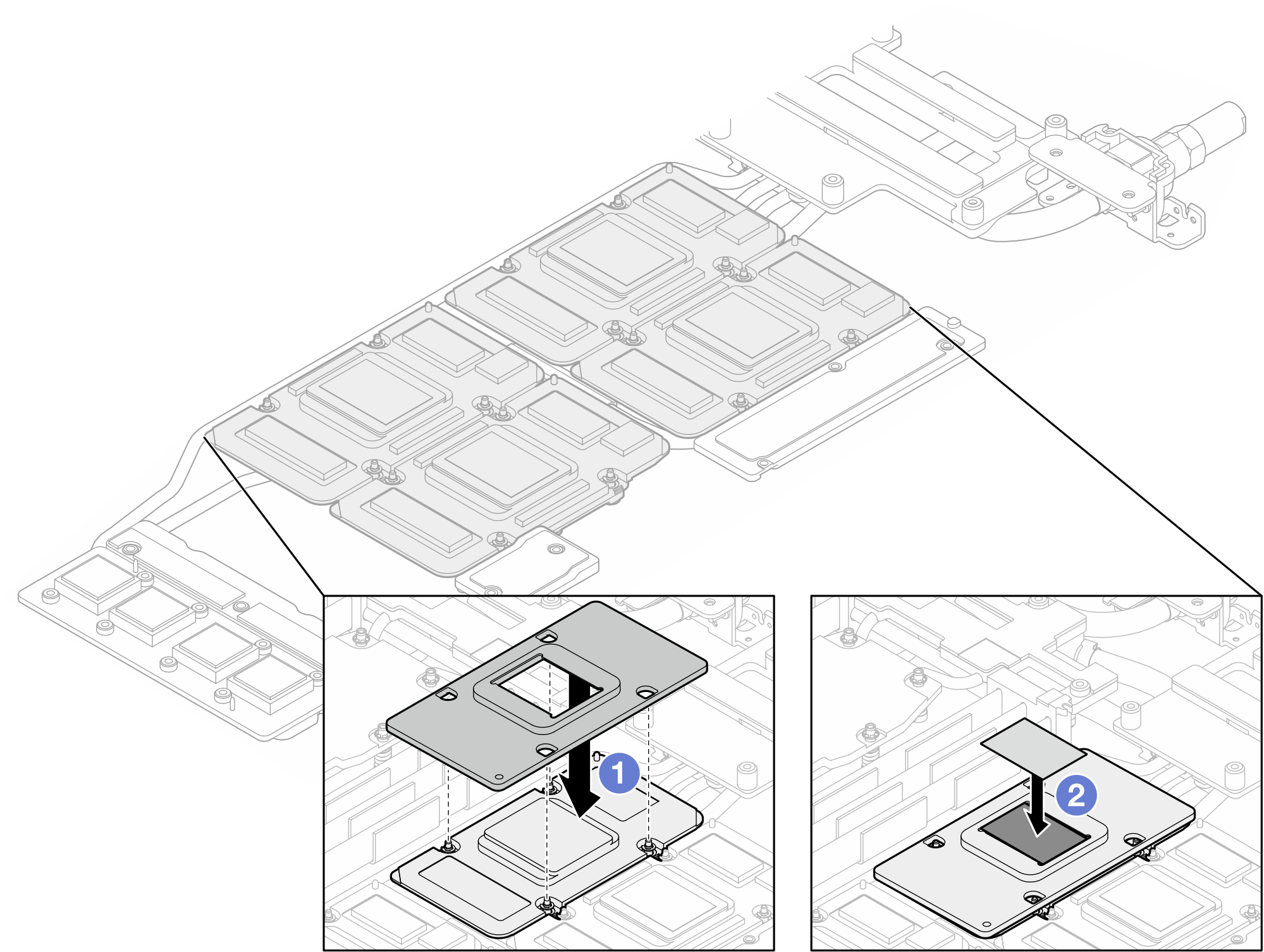
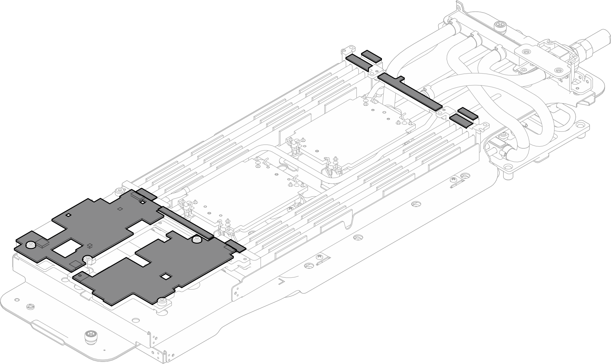
- Replace the putty pads on the GPU node water loop.Figure 12. Water loop putty pads replacement (GPU node)
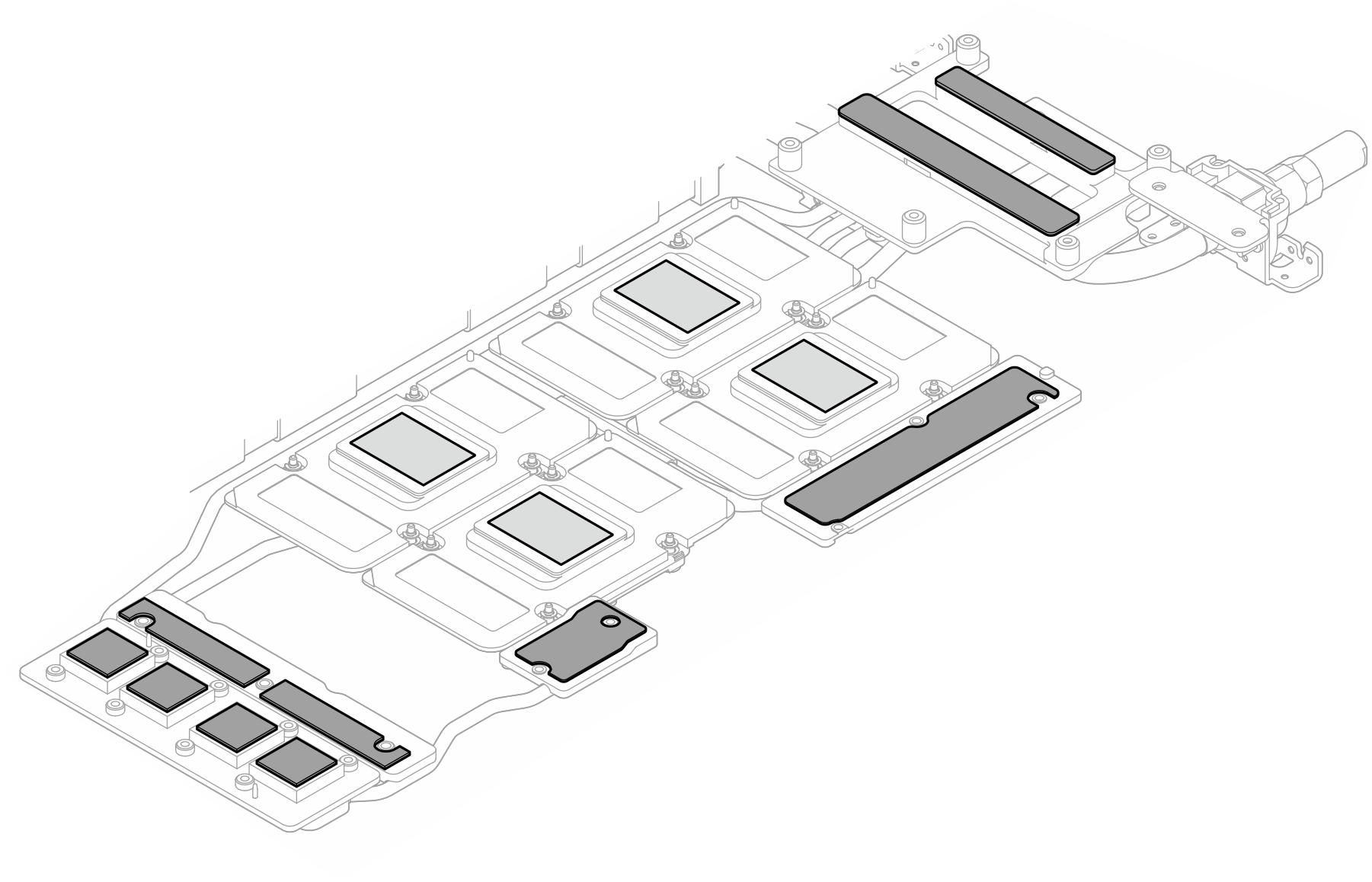
- Replace the putty pads (x5) on the GPU. Make sure to align the putty pads to the GPU VR (1) and the markings on GPU. Repeat to replace all putty pads on the four GPUs.
1 GPU VR (Cover the GPU VR with putty pad) Figure 13. GPU putty pads replacement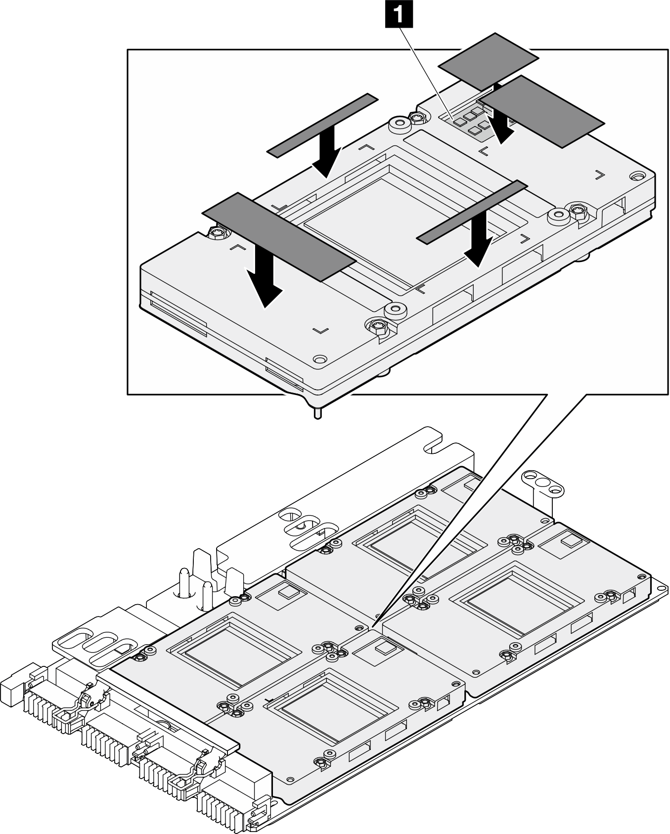
Make sure to follow Gap pad/putty pad replacement guidelines.
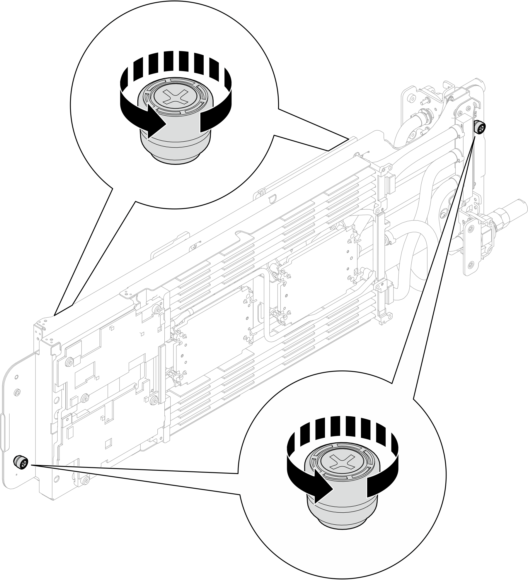
- Fully loosen two captive thumbscrews located at each end of the water loop carrier.Figure 14. Loosening water loop captive thumbscrews
- Install the compute node side of the water loop into the compute node of the tray.
- Carefully hold the water loop with both hands and flip it.
- Carefully position the water loop onto the two guide pins near the rear of the node; then, gently lower down the water loop and ensure it is seated firmly on the system board.
Figure 15. Water loop carrier installation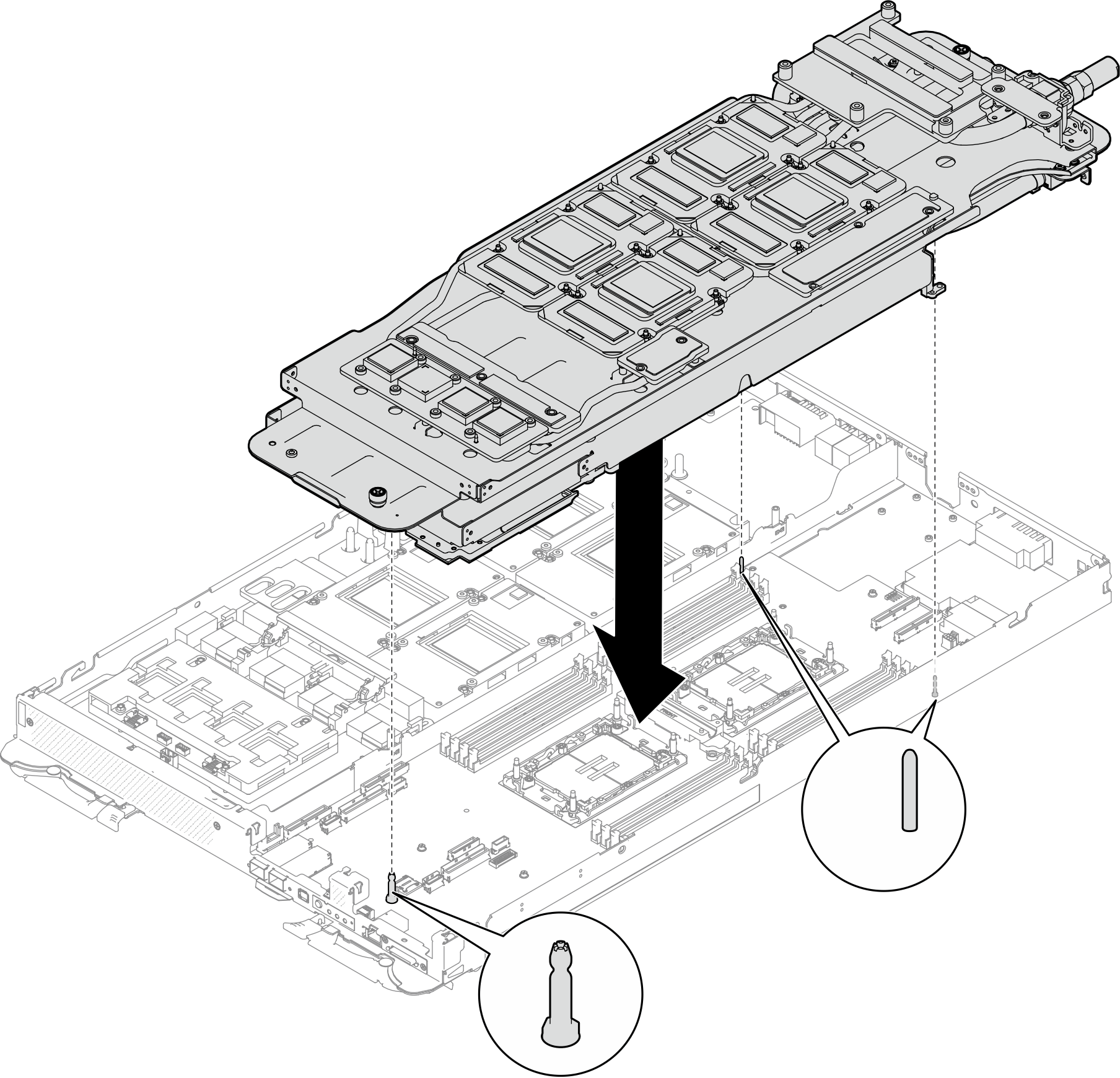
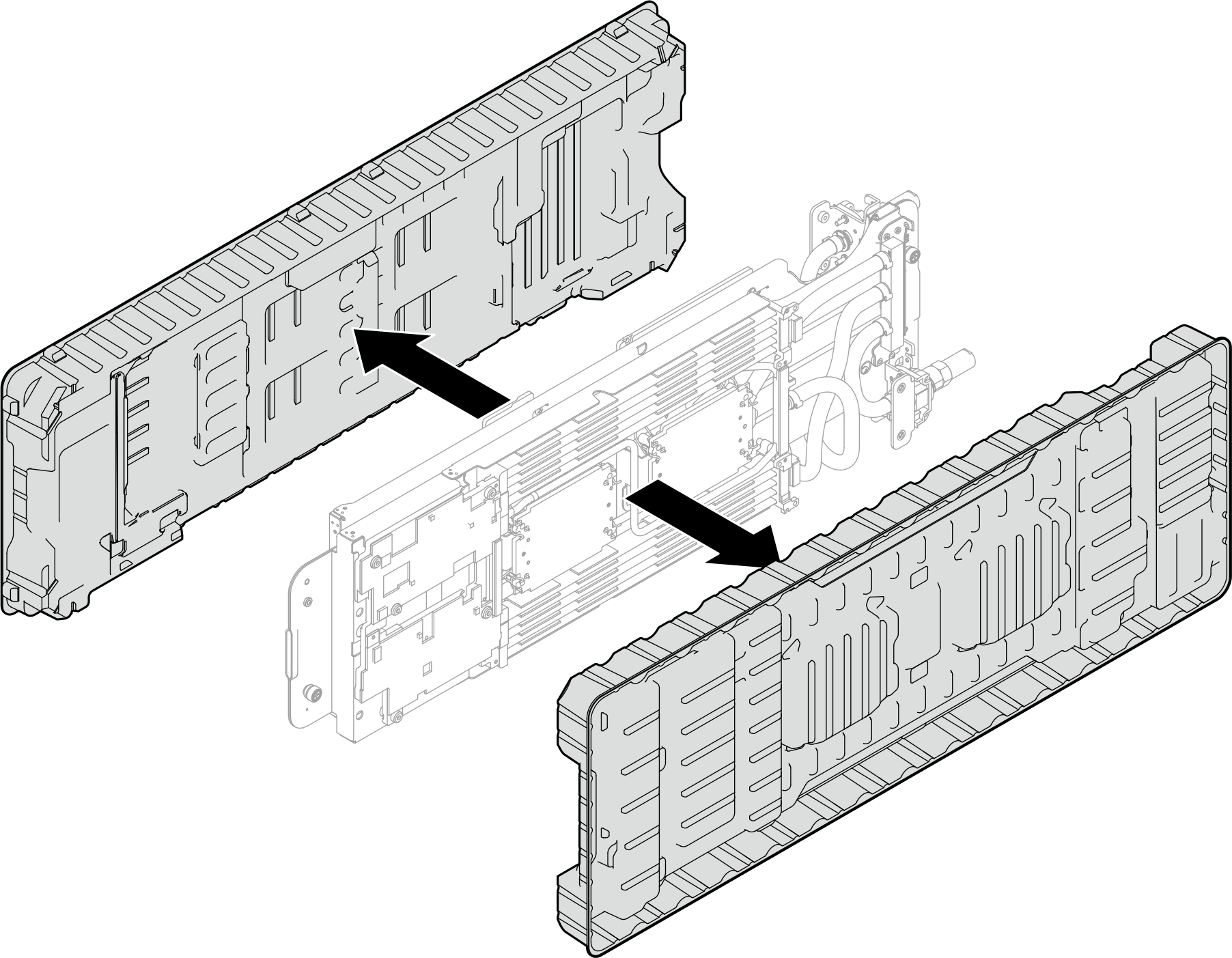
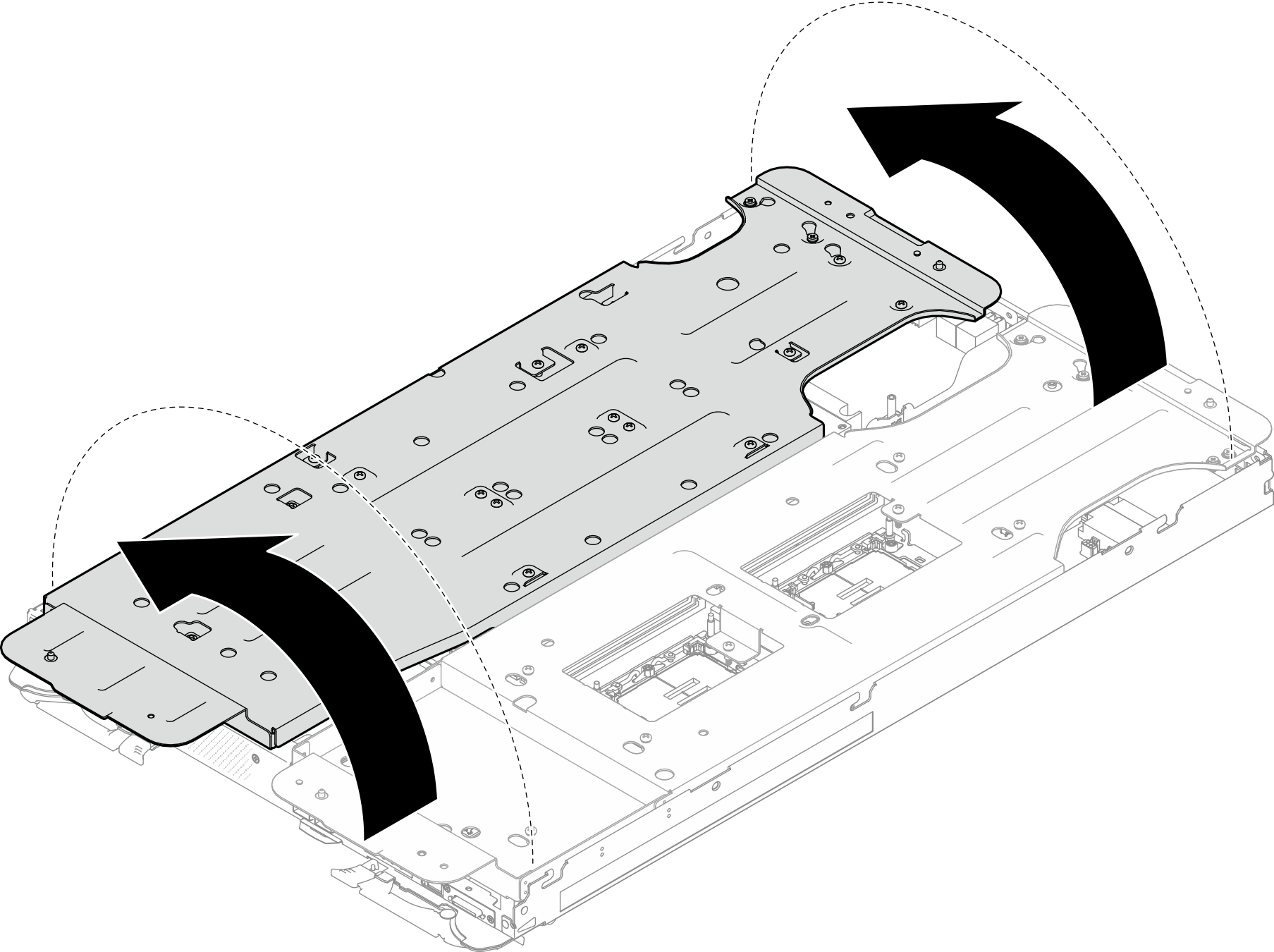
- Unfold and install the other side of the water loop as shown.Figure 16. Unfolding water loop
- Ensure the processors are secured properly.
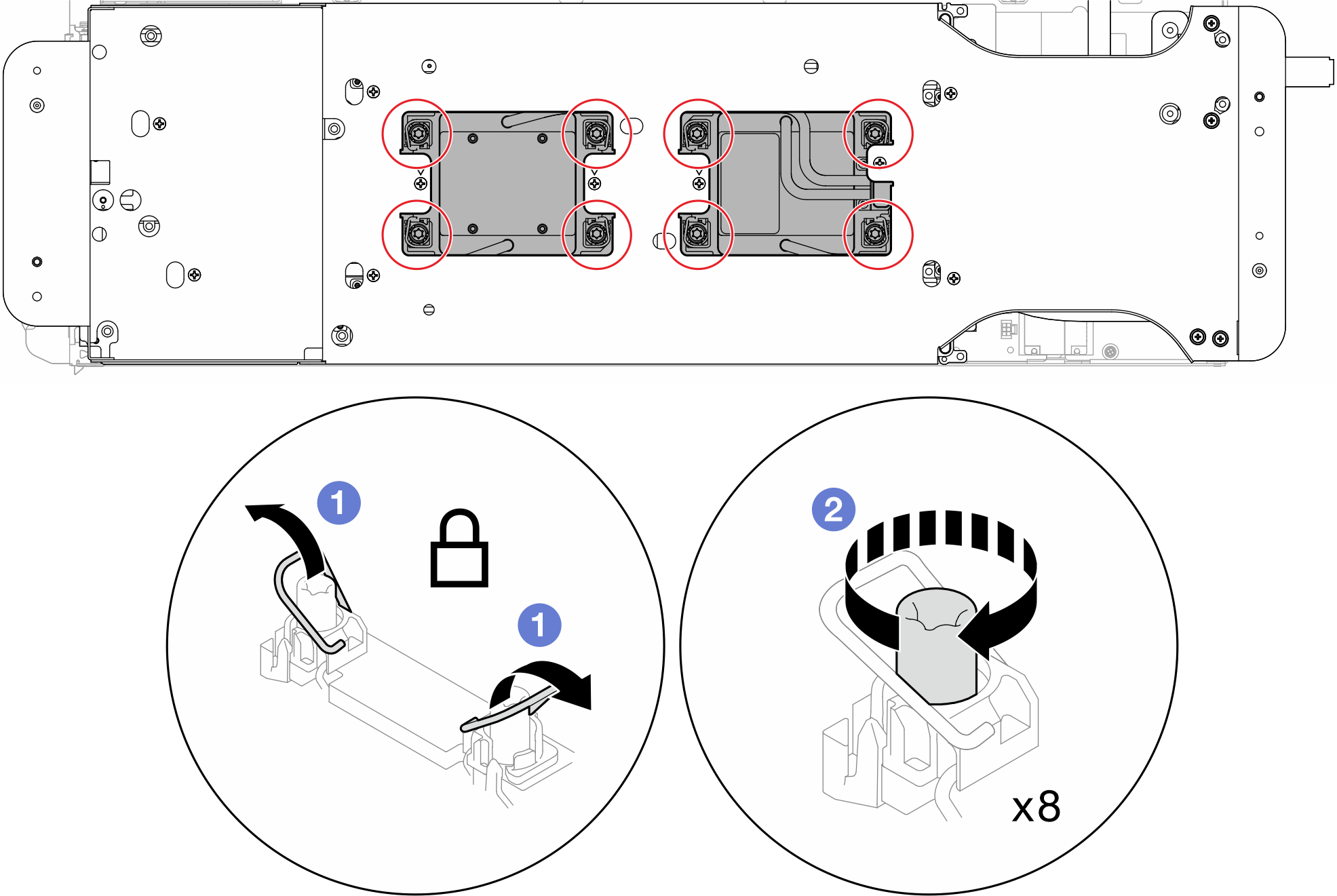
- Rotate 8x anti-tilt wire bails outwards to the locked position.
- Fully tighten 8x Torx T30 captive screws on cold plates with a general screwdriver, following the installation sequence shown on the cold plate label.NoteFor reference, the torque required for the screws to be fully tightened/removed is 10+/- 2.0 lbf-in, 1.1+/- 0.2 N-m.AttentionTo prevent damage to components, make sure that you follow the indicated tightening sequence.Figure 17. Securing Torx T30 captive screws
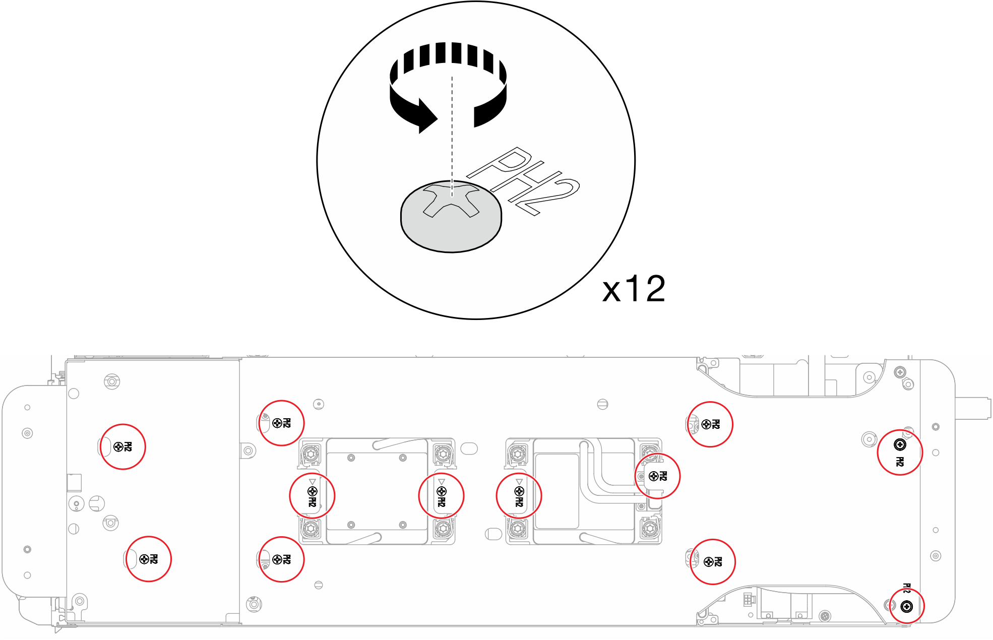
- Loosen water loop carrier screws (x12 Phillips #2 screws for two nodes).Figure 18. Loosening water loop carrier screws
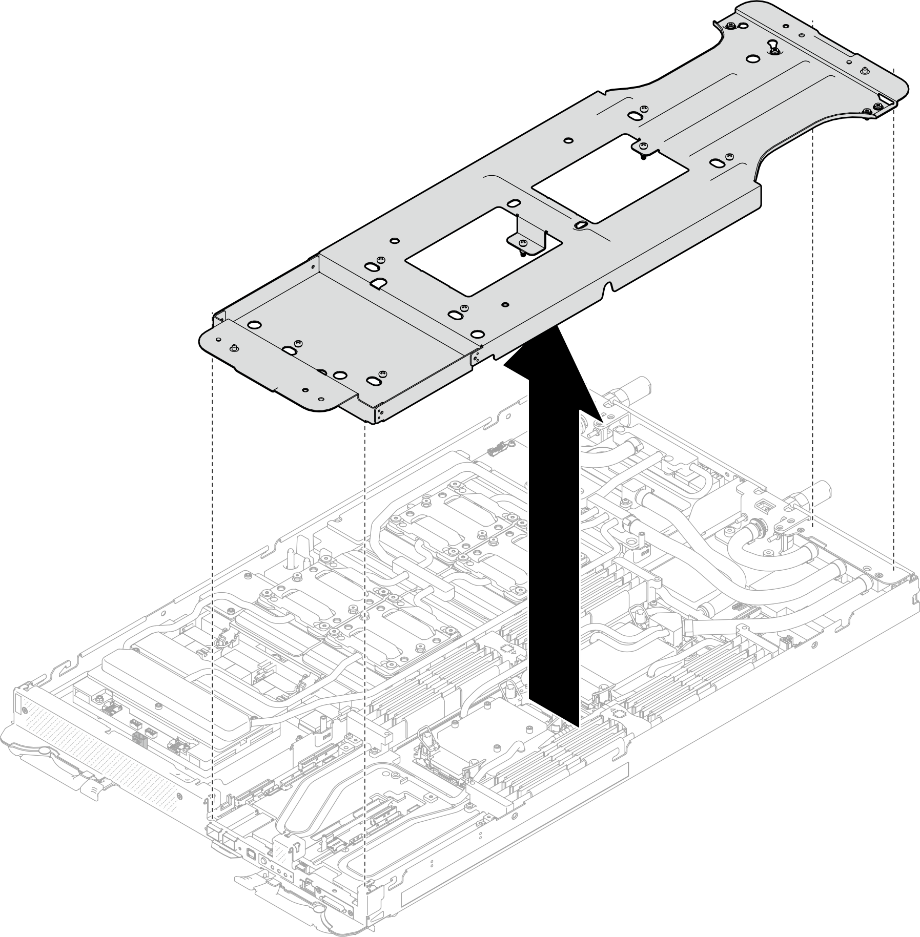
- Carefully lift each water loop carrier up and away from the water loop one at a time.Figure 19. Water loop carrier removal
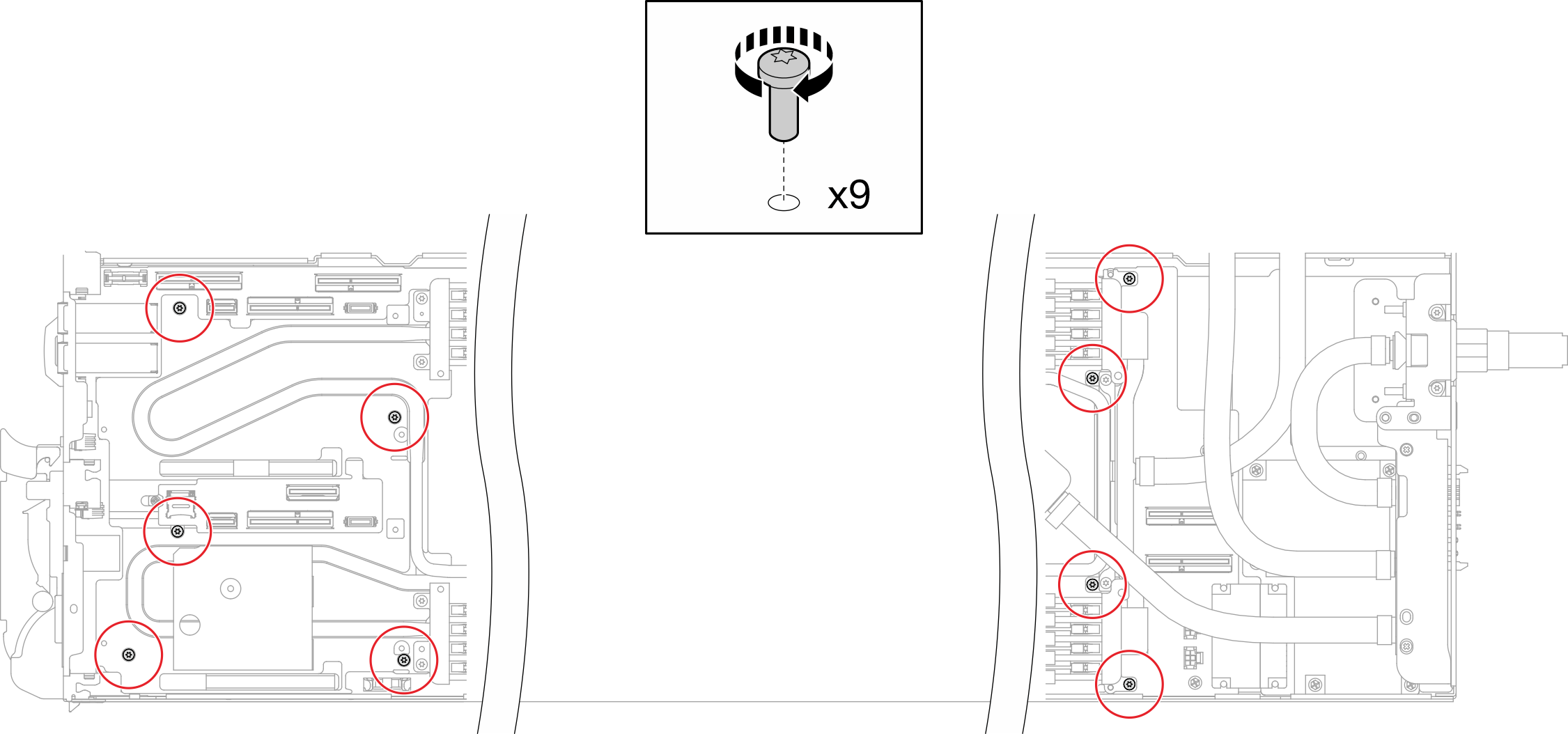
- Install water loop screws (9x Torx T10 screws per node) with a torque screwdriver set to the proper torque.NoteFor reference, the torque required for the screws to be fully tightened/removed is 5.0+/- 0.5 lbf-in, 0.55+/- 0.05 N-M.Figure 20. Water loop screws installation
- Install the Torx T10 screws (x7 screws) to secure the quick connect.Figure 21. Quick connect screw installation
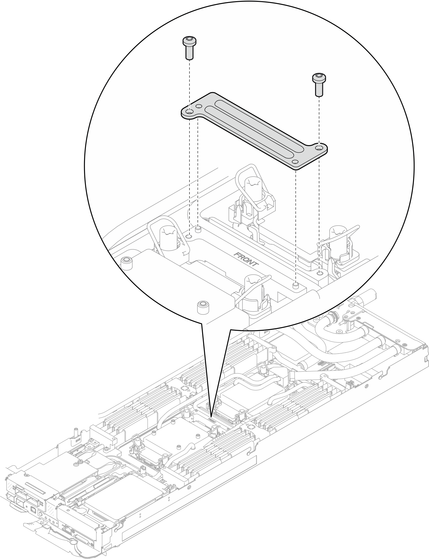
- Install two VR clamp plates into the nodes and install Torx T10 screws (4x Torx T10 screws for two nodes).Figure 22. VR clamp plate installation
- Replace the putty pads on the top side and the bottom side of the OSFP module conduction plate. Figure 23. OSFP module conduction plate putty pads replacement
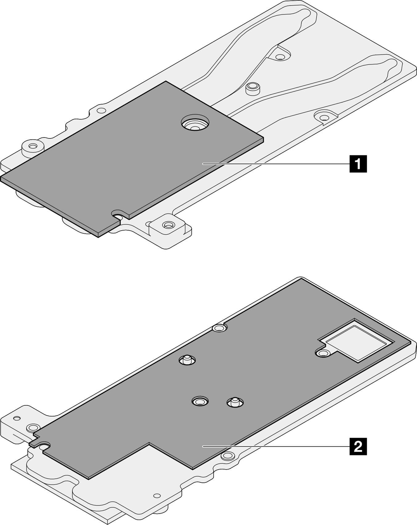
1 Conduction plate top putty pad
2 Conduction plate bottom putty pad
Make sure to follow Gap pad/putty pad replacement guidelines.
- Install the OSFP module conduction plate onto the water loop.
Screw Type Screwdriver Type 1 M3x5 screw (x3) Phillips #1 head screwdriver 2 M3 screw (x2) T10 screwdriver Figure 24. Installing the OSFP module conduction plate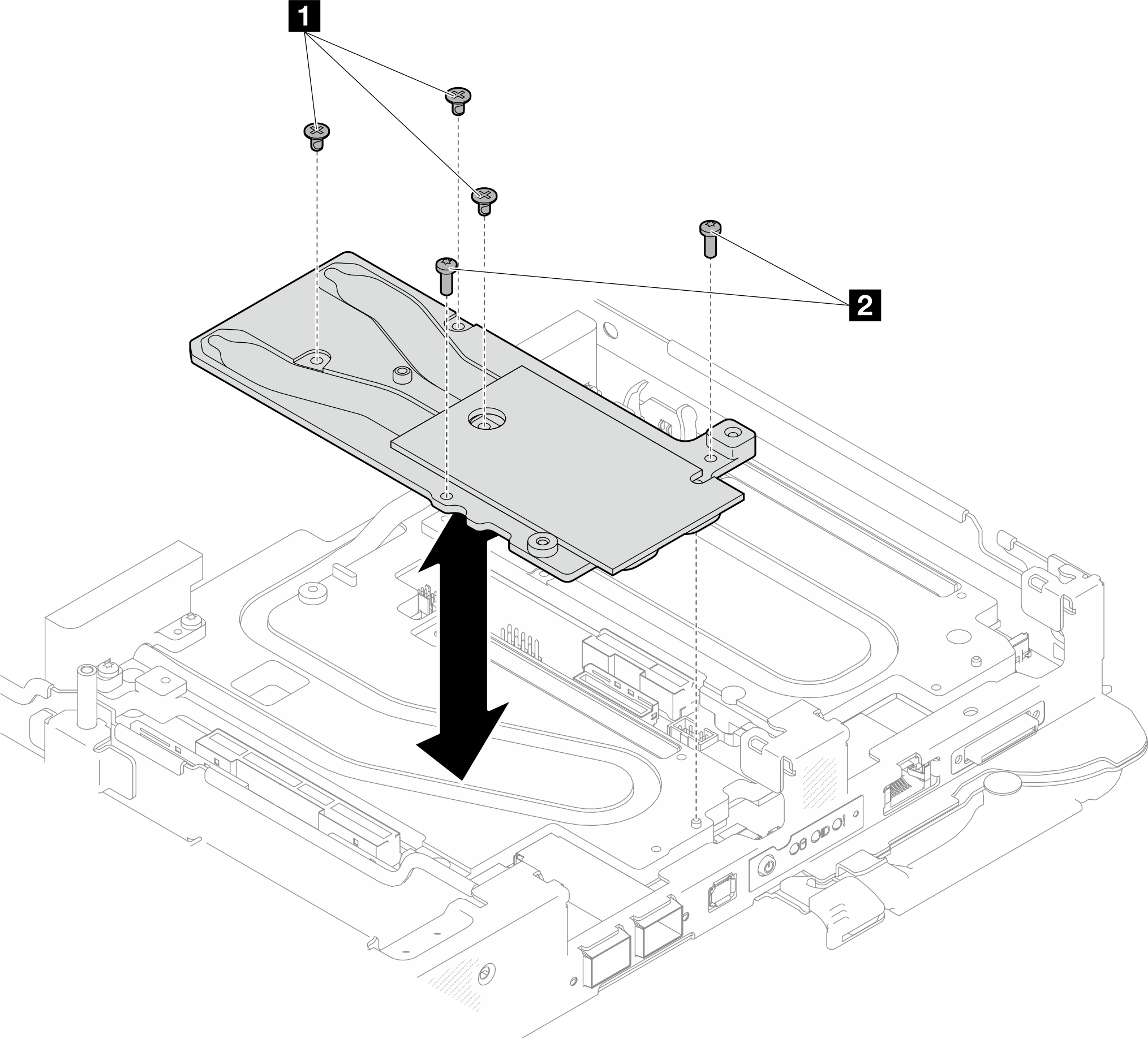
- Install the two Hex screws to the OSFP module with a 4.5 mm hex head screwdriver.Figure 25. OSFP module conduction plate Hex screws installation
Install water loop to the GPU node
- Loosen water loop carrier screws (x20 Phillips #2 screws).Figure 26. Water loop screws and quick connect screws installation (GPU node)
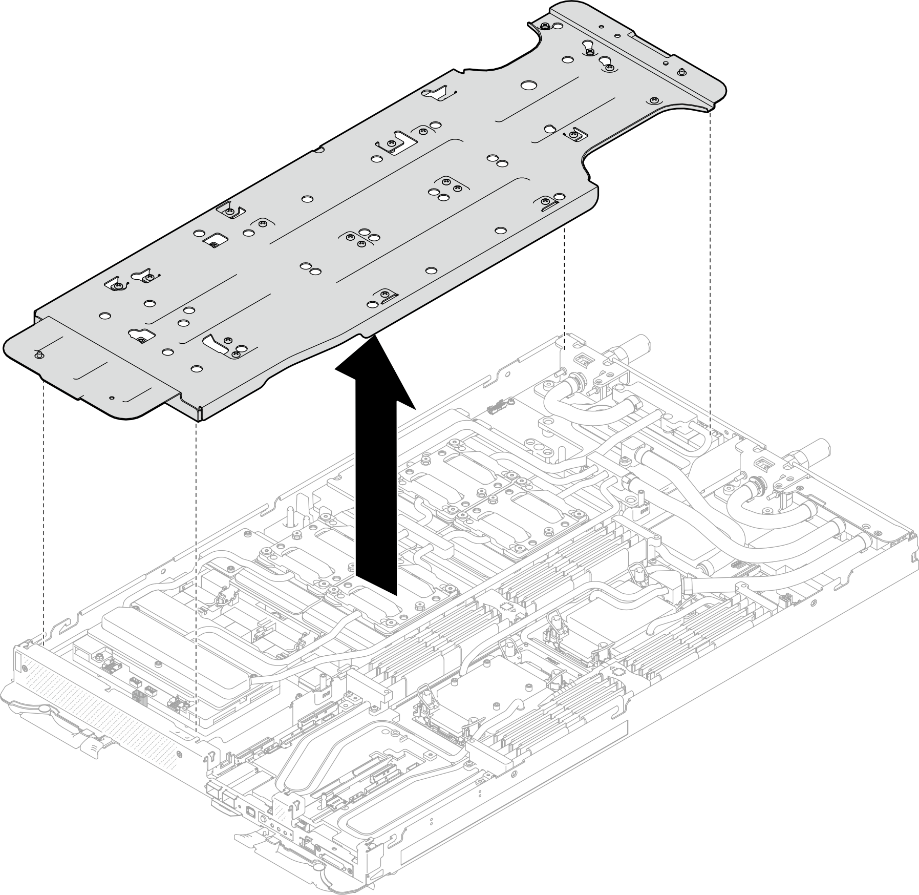
- Remove the water loop carrier from the GPU node.Figure 27. Water loop carrier removal (GPU node)
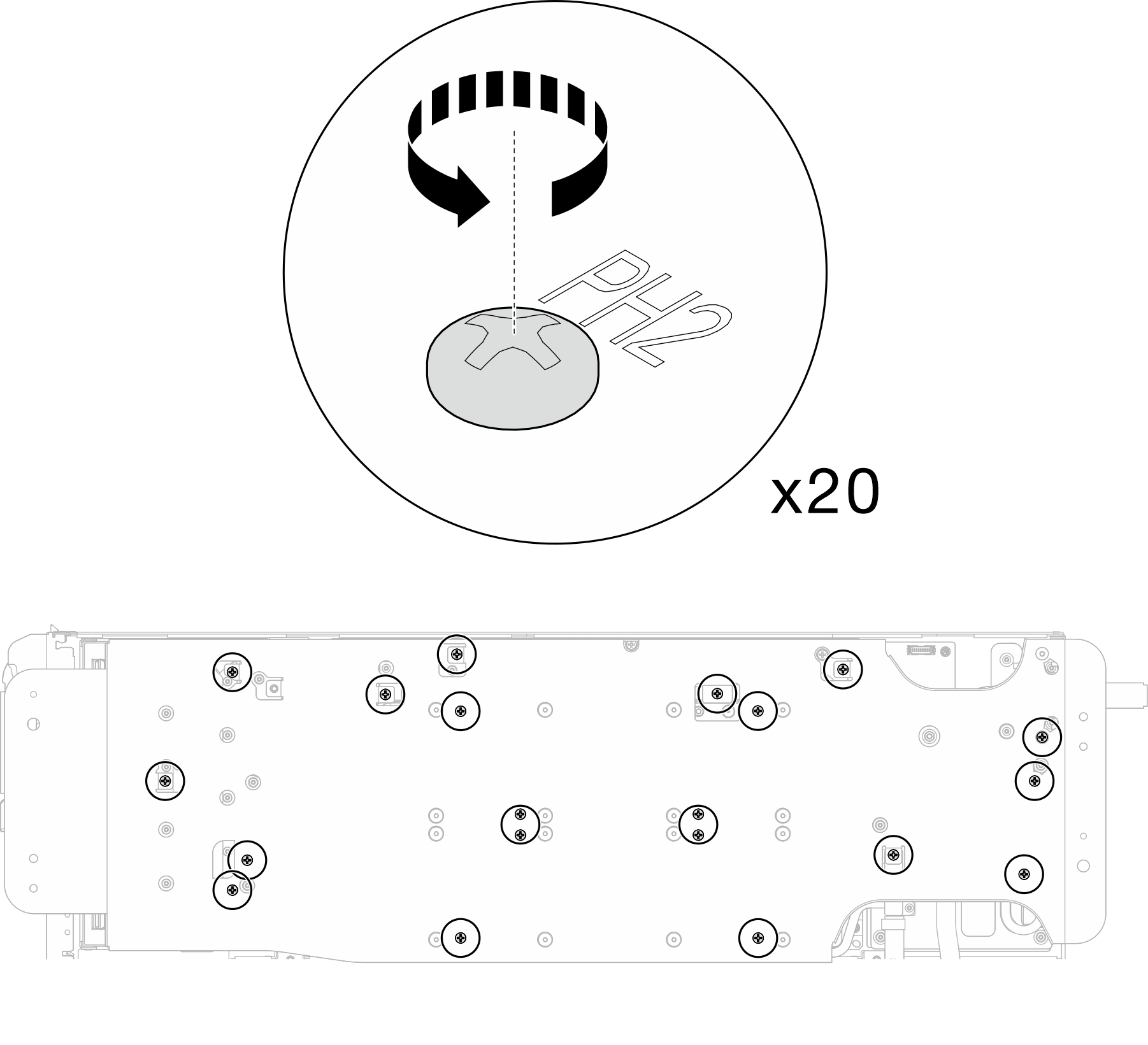
- Install GPU cold plate screws (x16 PH2 screws). Install the GPU cold plates in diagonal pattern. Complete installing screws of , then proceed to .
- Follow the screw installation sequence: → →
 →
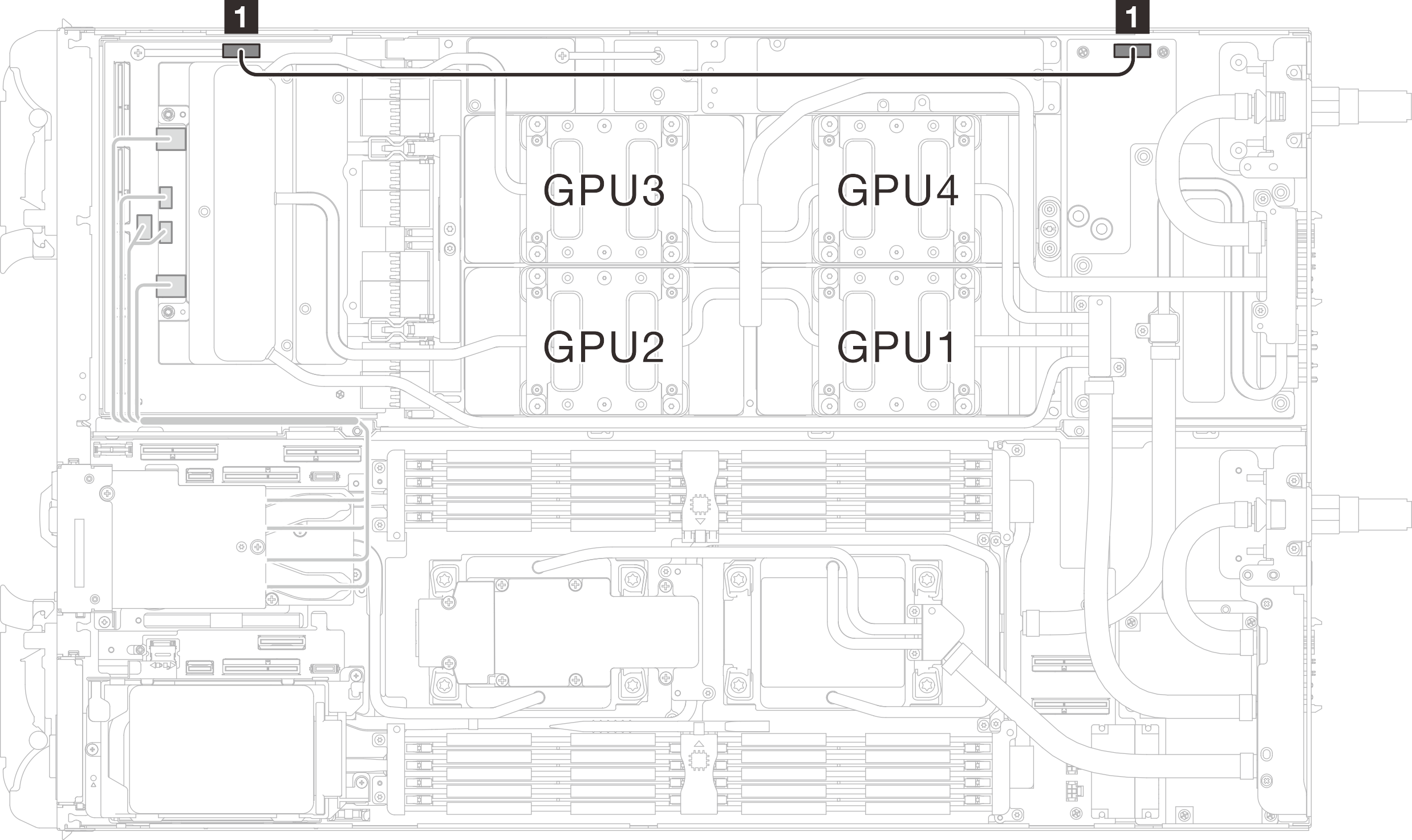
→  NoteMake sure to follow screw installation sequence to prevent GPU cold plate tilting.The following illustration shows the GPU numbering.Figure 28. GPU numbering
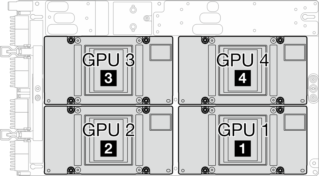
Figure 29. GPU cold plate screw installation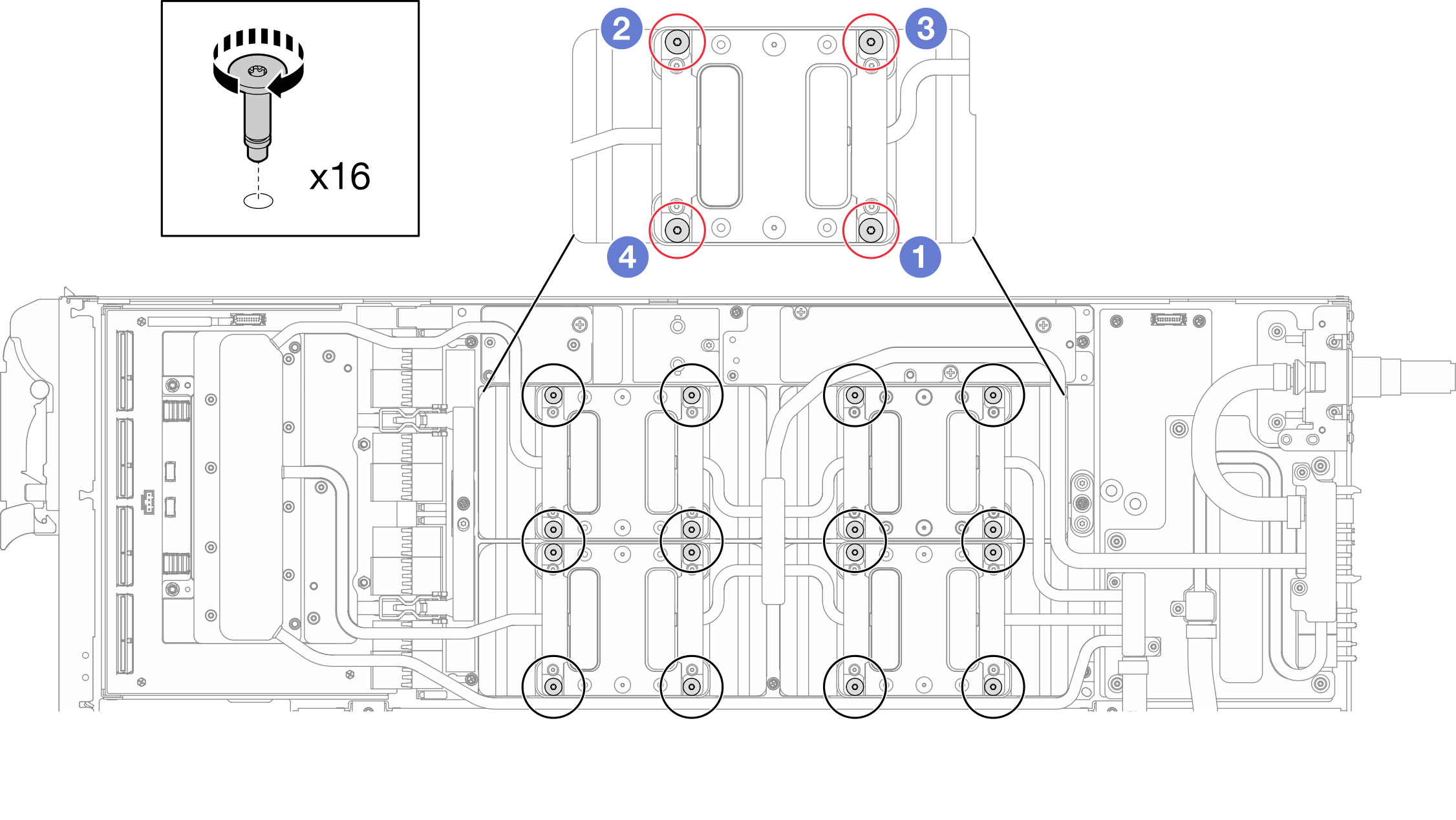
- Follow the screw installation sequence:
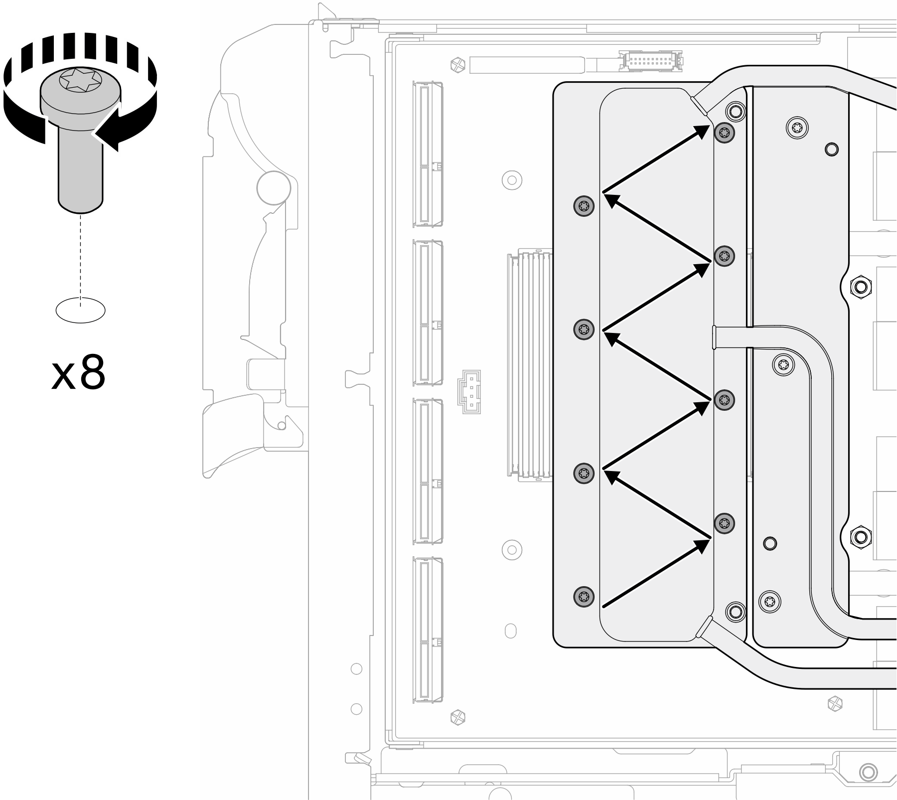
- Follow the screw installation sequence specified on the network board label, and install network cold plate screws (x8 Torx T10 screws) with a torque screwdriver set to the proper torque.NoteFor reference, the torque required for the screws to be fully tightened/removed is 5.0+/- 0.5 lbf-in, 0.55+/- 0.05 N-M.Figure 30. Network card screw installation
- Install the quick connect screws (x4 Torx T10) with a torque screwdriver set to the proper torque.NoteFor reference, the torque required for the screws to be fully tightened/removed is 5.0+/- 0.5 lbf-in, 0.55+/- 0.05 N-M.Figure 31. Quick connect screw installation (GPU node)
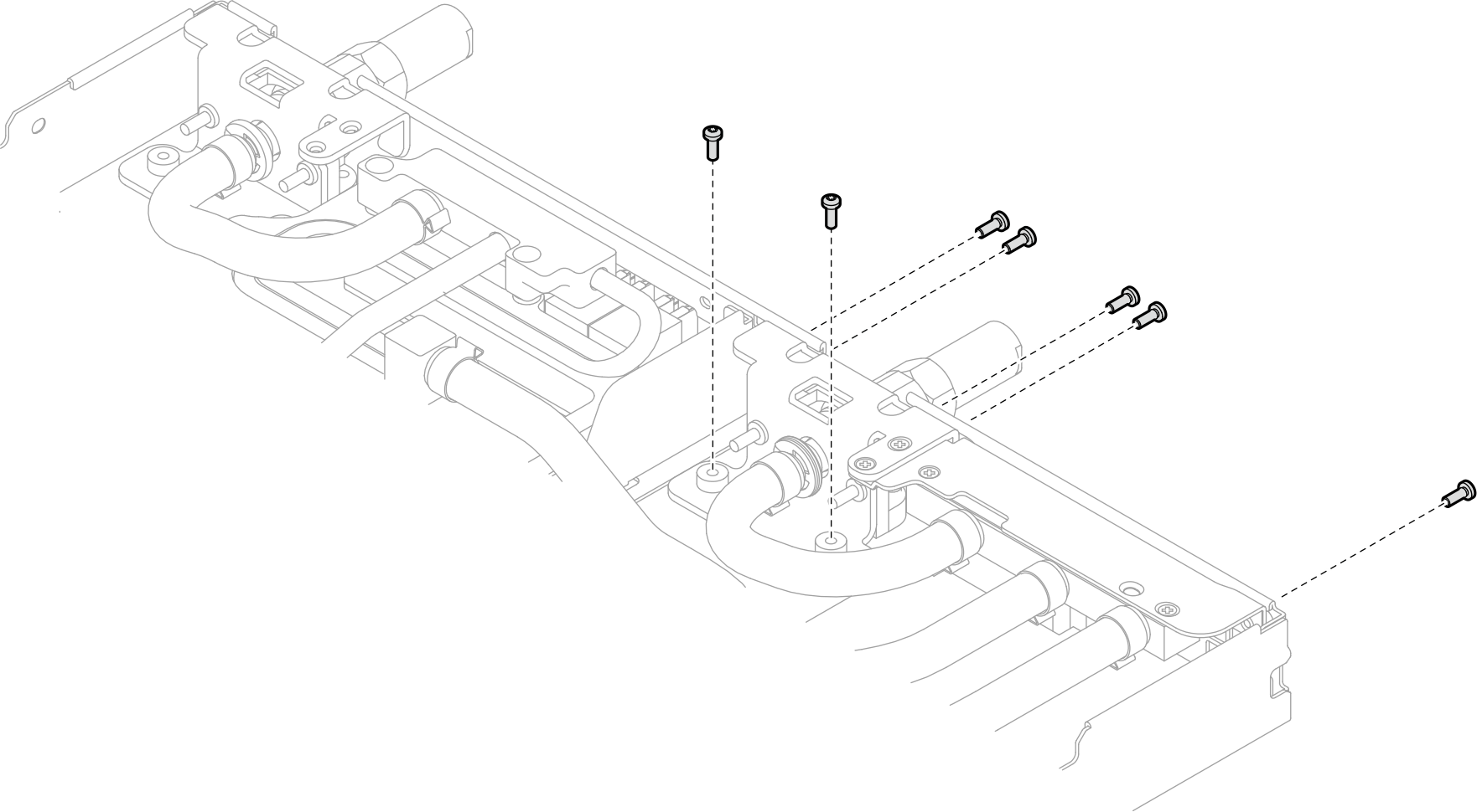
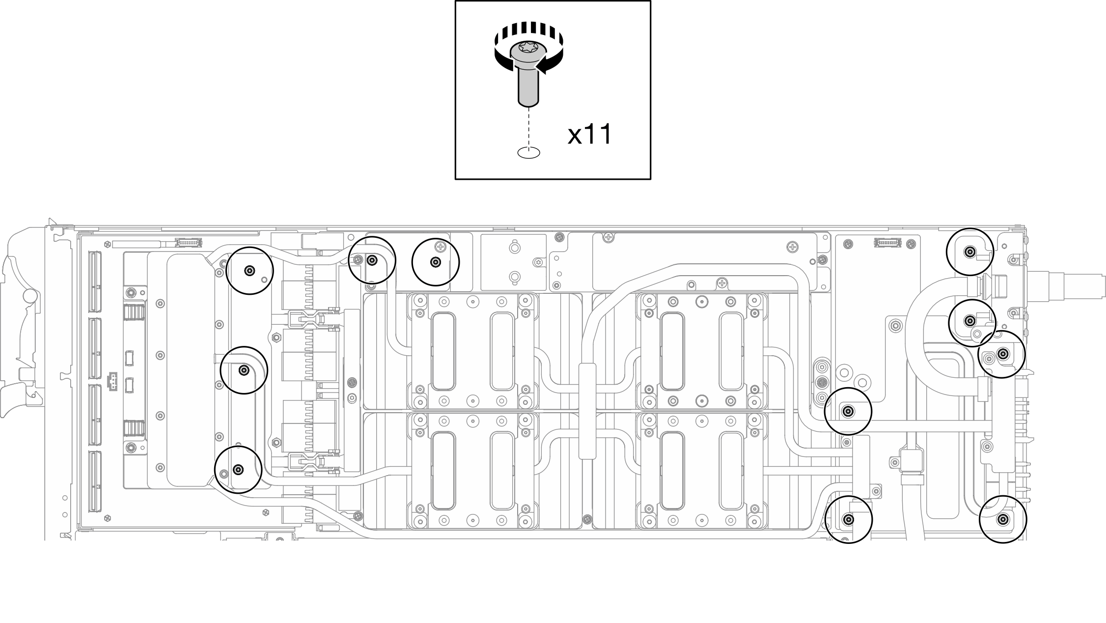
- Install water loop screws and quick connect screws (x11 Torx T10 screws) with a torque screwdriver set to the proper torque.NoteFor reference, the torque required for the screws to be fully tightened/removed is 5.0+/- 0.5 lbf-in, 0.55+/- 0.05 N-M.Figure 32. Water loop Torx T10 screws installation (GPU node)
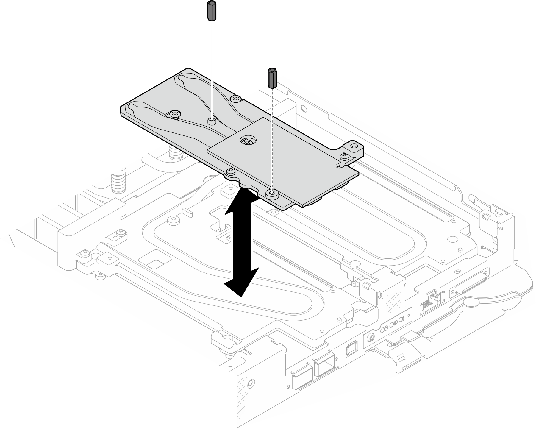
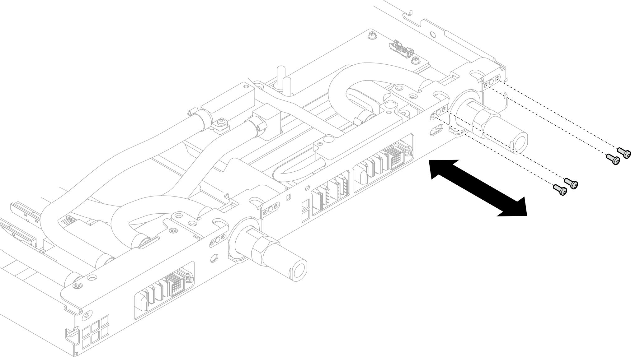
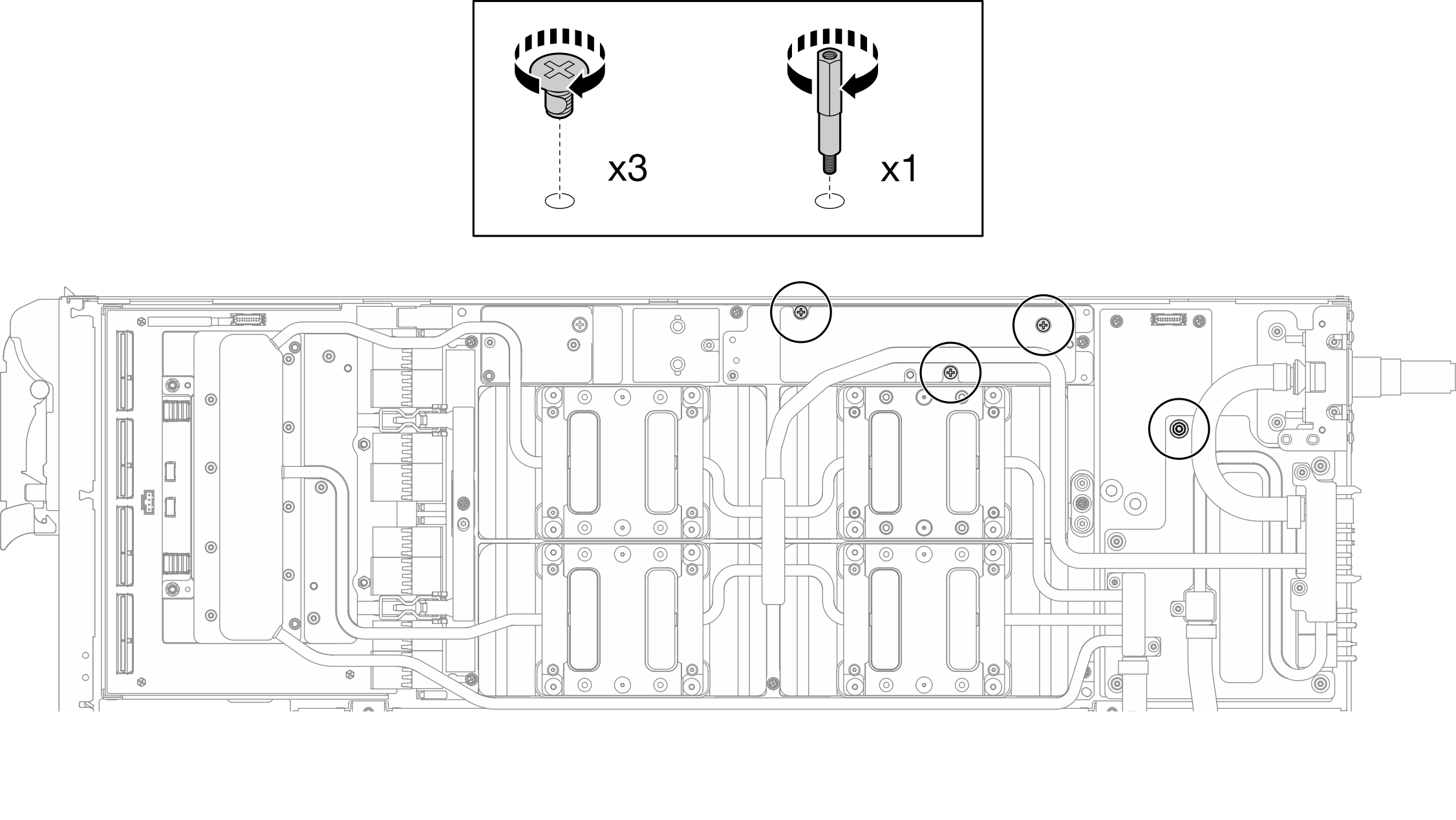
- Install the Hex screw (x1) and the PH1 screws (x3).NoteFor reference, the torque required for the screws to be fully tightened/removed is 5.0+/- 0.5 lbf-in, 0.55+/- 0.05 N-M.Figure 33. Water loop Hex and PH1 screws installation (GPU node)
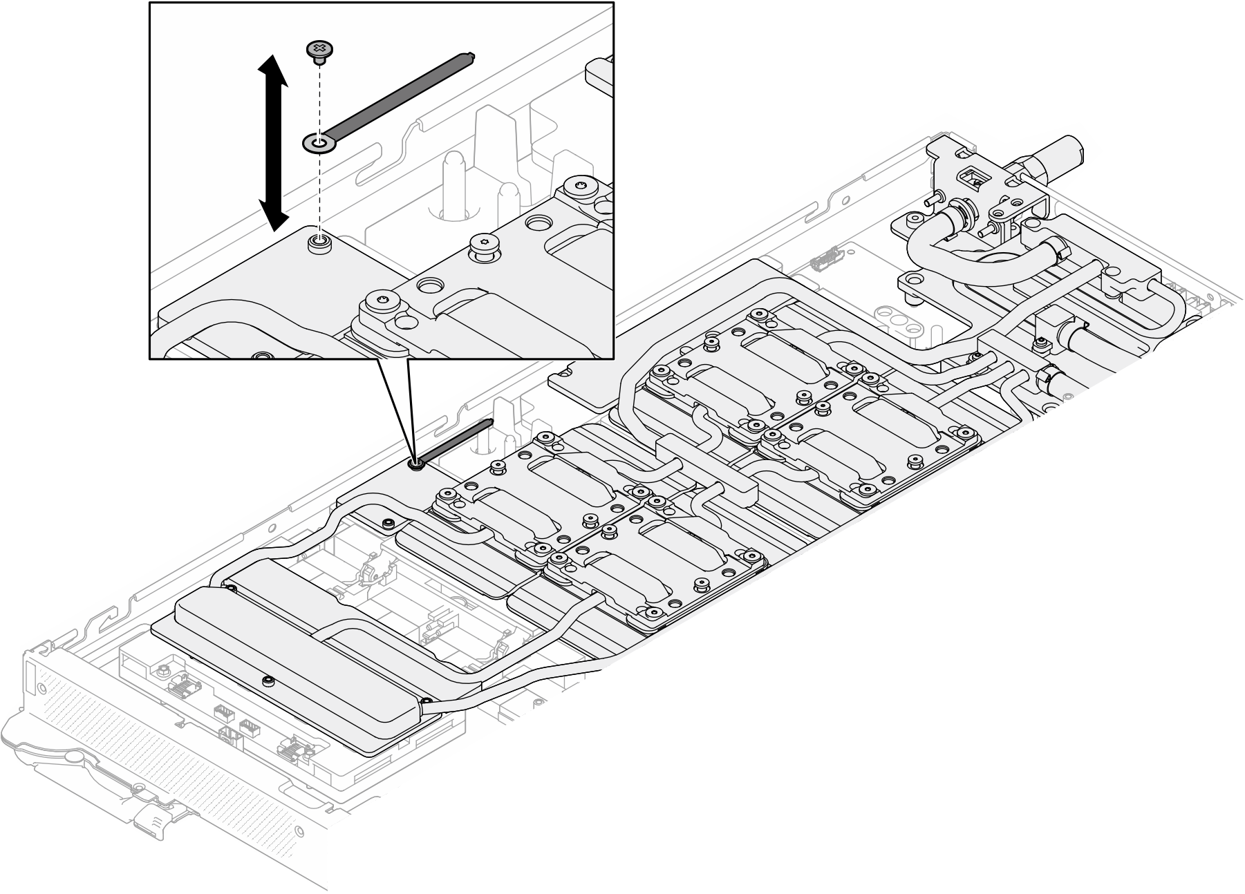
- Install the cable tie to the GPU board.Figure 34. Installing the cable tie
- Connect the carrier board power cable.Figure 35. Connecting carrier board power cable
From (carrier board) To (GPU node power distribution board) 1 Power and side band connector 1 Power connector
Install the OSFP module. See Install the OSFP module.
Install the drive cage. Depending on system configurations, see Install a drive cage assembly, Install a 7mm NVMe drive cage assembly, or Install the E3.S drive cage assembly.
Install the MCIO cables. Follow the guidance and routing information in Internal cable routing.
Install the bus bar. See Install the bus bar.
Install the M.2 backplane assembly. See Install the M.2 backplane assembly.
Install the memory modules. See Install a memory module.
Install the DIMM comb. See Install a DIMM comb.
Install the cross braces. See Install the cross braces.
Install the tray cover. See Install the tray cover.
Install the tray into the enclosure. See Install a DWC tray in the enclosure.
- Connect all required external cables to the solution.NoteUse extra force to connect QSFP cables to the solution.
Check the power LED on each node to make sure it changes from fast blink to slow blink to indicate all nodes are ready to be powered on.