Install the power distribution board
Use this information to install the power distribution board.
About this task
To identify the gap pad/putty pad location and orientation, see:
Required Tools list in the following section.
Before replacing the gap pad/putty pad, gently clean the interface plate or the hardware surface with an alcohol cleaning pad.
Hold the gap pad/putty pad carefully to avoid deformation. Make sure no screw hole or opening is blocked by the gap pad/putty pad material.
Do not use expired putty pad. Check the expiry date on putty pad package. If the putty pads are expired, acquire new ones to properly replace them.
Required tools
Make sure you have the required tools listed below in hand to properly replace the component.
Compute node water loop carrier
(The water loop carrier in the Service Kit is reusable, it is recommended to keep it at the facility where the server operates for future replacement needs.)
SD665-N V3 Water Loop Gap Pad Kit
SD665-N V3 Miscellaneous Parts Kit
SD665-N V3 Water Loop Putty Pad Kit
SD665-N V3 OSFP Putty Pad Kit
Putty pad cannot be reused. Whenever the water loop is removed, putty pads must be replaced with new ones before reinstalling the water loop.
Drive gap pad or putty pad kits according to the drives installed in the tray. See their respective replacement procedures for more information.
Screws and screwdrivers
Prepare the following screwdrivers to ensure you can install and remove corresponding screws properly.Screwdriver Type Screw Type Hex screw (GPU node water loop) 6 mm hex head screwdriver Hex screw (OSFP module conduction plate) 4.5 mm hex head screwdriver Torx T10 head screwdriver Torx T10 screw Torx T20 head screwdriver Torx T20 screw Phillips #2 head screwdriver Phillips #2 screw 3/16" hex head screwdriver M3 screw
Read Installation Guidelines and Safety inspection checklist to ensure that you work safely.
Go to Drivers and Software download website for ThinkSystem SD665-N V3 to see the latest firmware and driver updates for your server.
Go to Update the firmware for more information on firmware updating tools.
Procedure
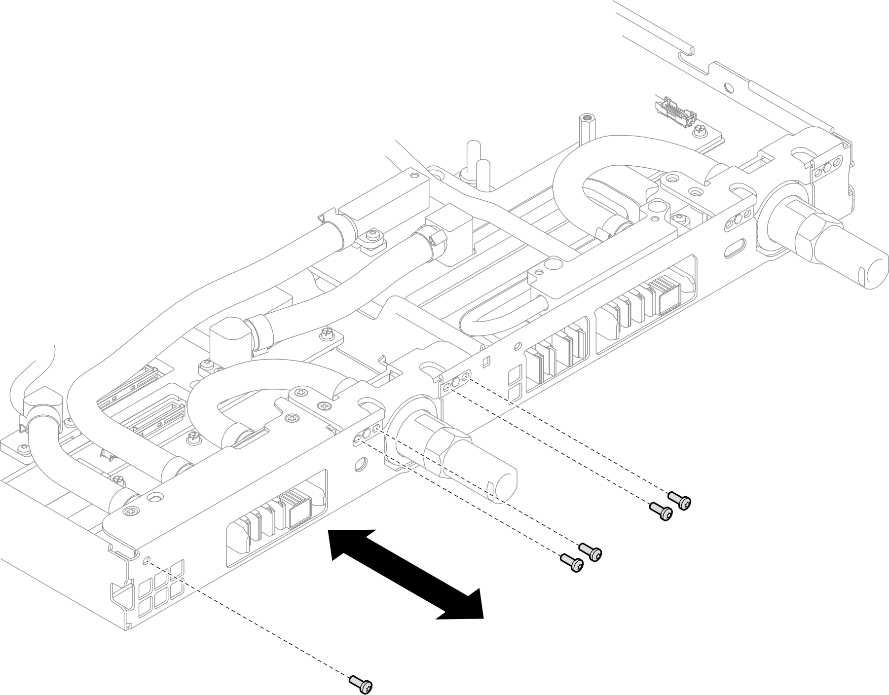
- Install the power distribution board.
 Tilt the power distribution board and align it with the hole; then, slide it into place.
 Gently push the power distribution board connector to ensure it is connected to the system board.
 Fasten the five M3 screws with a 3/16" hex head screwdriver.
NoteUse a 3/16" hex head screwdriver to ensure the proper removal and installation.
Figure 1. Power distribution board installation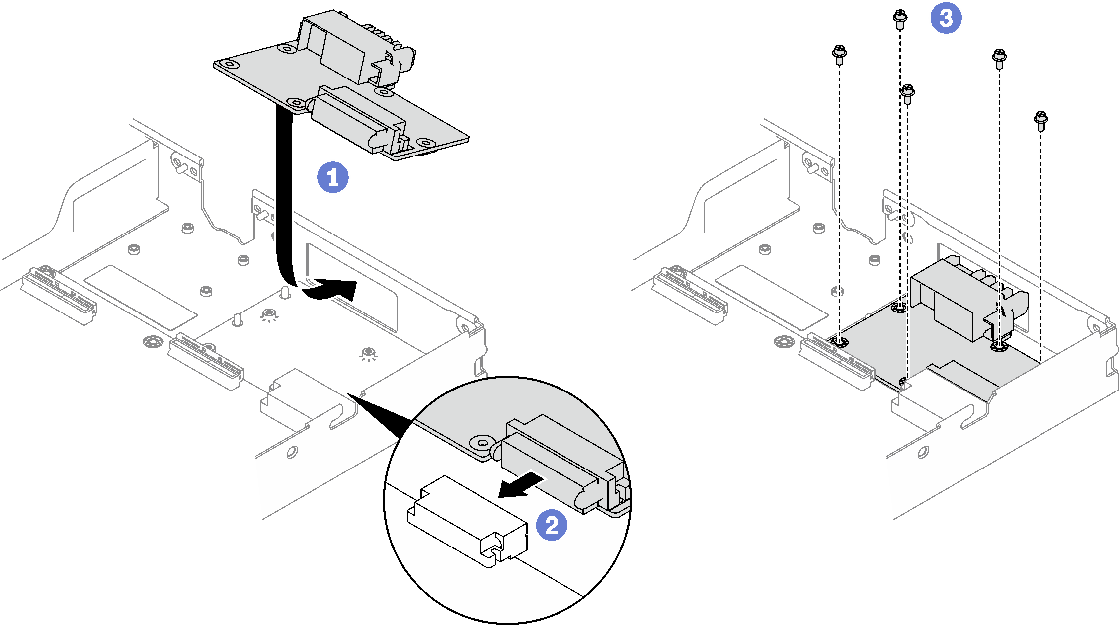
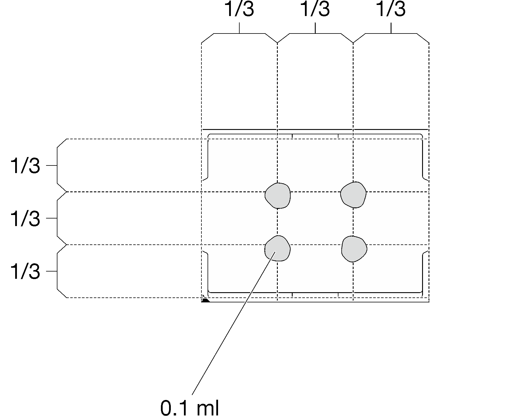
- Apply the thermal grease on the top of the processor with syringe by forming four uniformly spaced dots, while each dot consists of about 0.1 ml of thermal grease.NoteCarefully place the processor and retainer on a flat surface with the processor-contact side down.Figure 2. Thermal grease application
- Check the gap pads on the bottom side and top side of the water loop, if any of them are damaged or missing, replace them with the new ones. Figure 3. Water loop gap pads (bottom side)
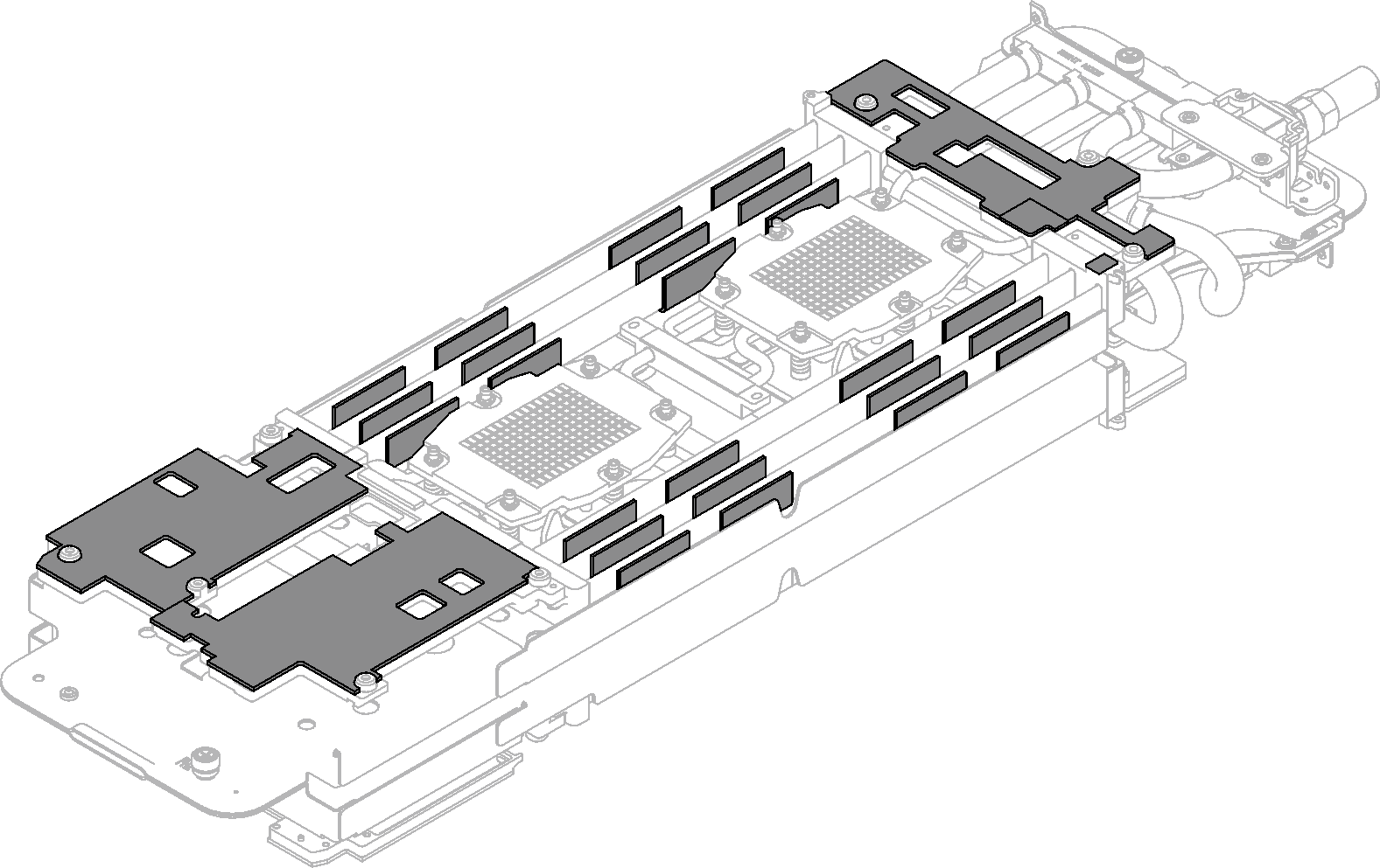 Figure 4. Water loop gap pads (top side)
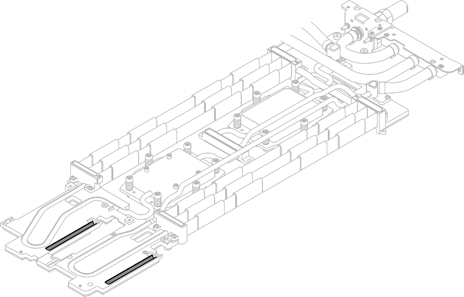
Make sure to follow Gap pad/putty pad replacement guidelines.
- Replace the putty pads on the water loop with new ones.AttentionPutty pad cannot be reused. Whenever a component is removed, putty pads must be replaced with new ones before reinstalling the component.Figure 5. Water loop putty pads
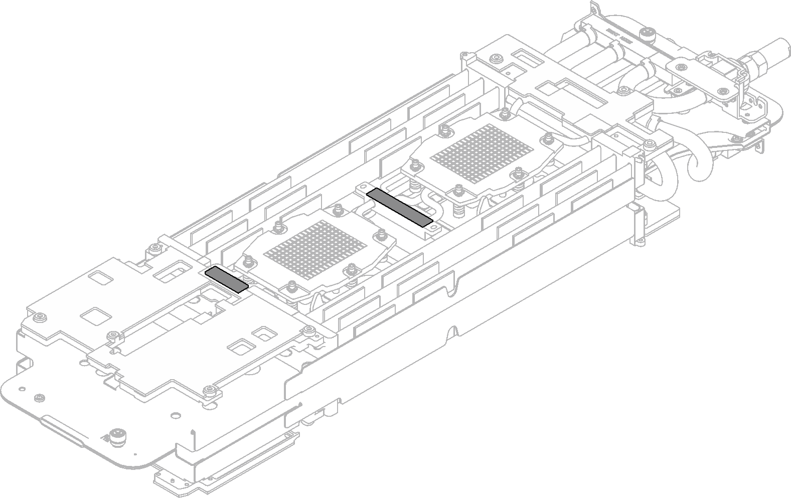
Make sure to follow Gap pad/putty pad replacement guidelines.
- Carefully rotate the top side of the water loop, position the water loop on the two guide pins near the rear of the node; then, gently put the water loop down and ensure it is firmly seated on the system board.AttentionMake sure to align the water loop with the three guide pins on the right side compute node.Figure 6. Guide pins on the compute node
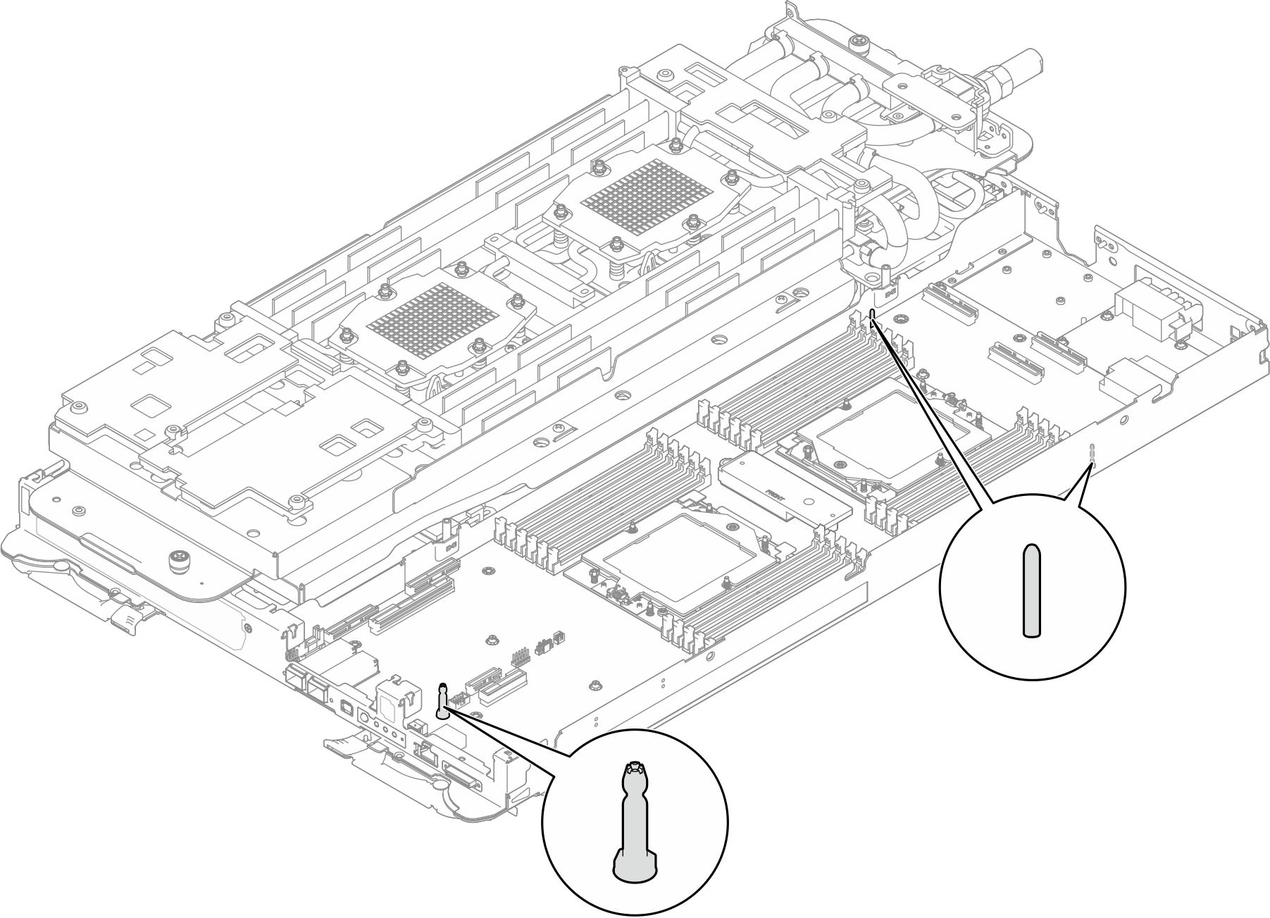 Attention
Slightly lift the water loop, then rotate it.
Do not tilt the water loop. Keep the water loop horizontal with the tray.
Install the water loop to the tray
Figure 7. Water loop installation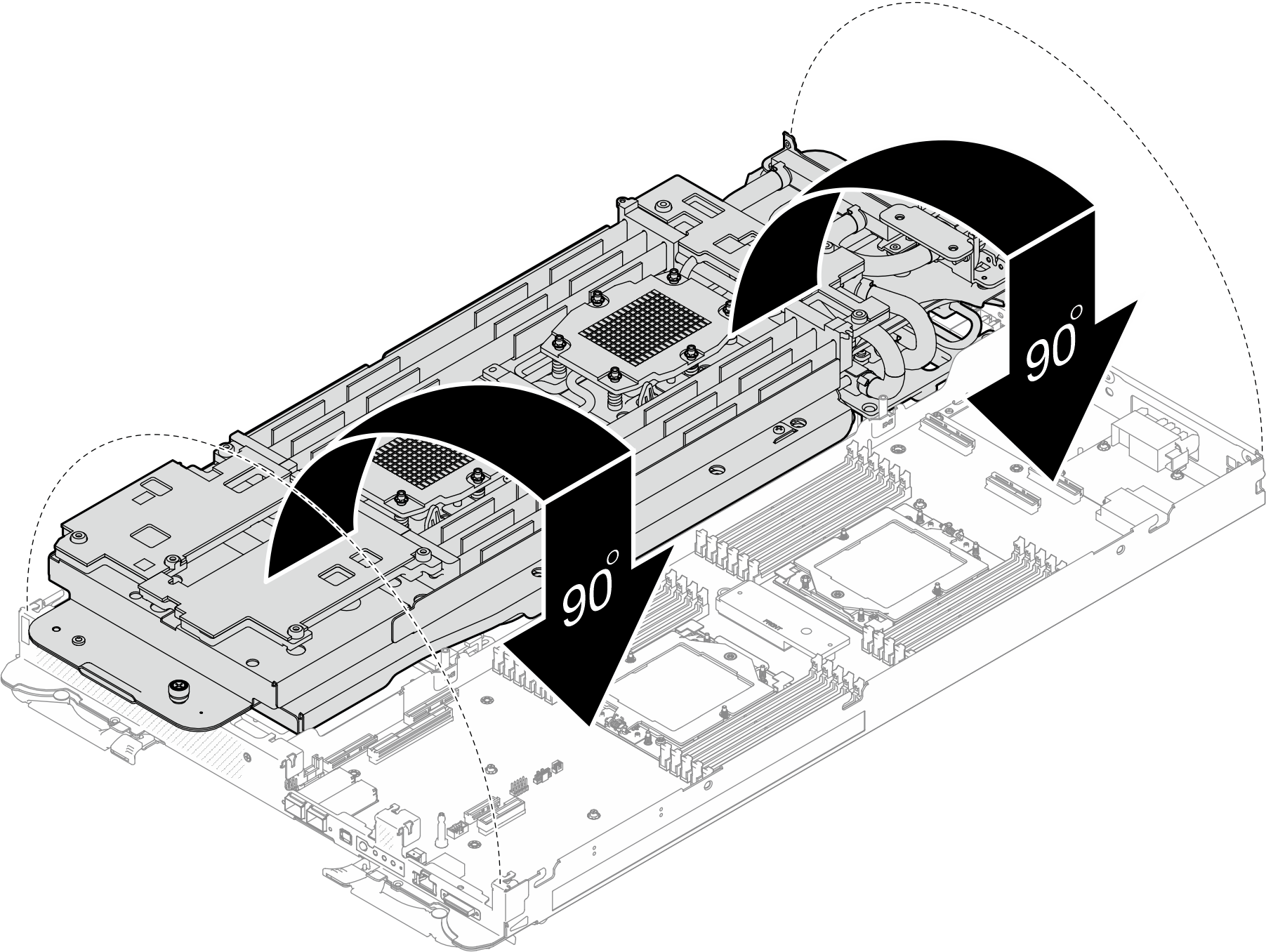
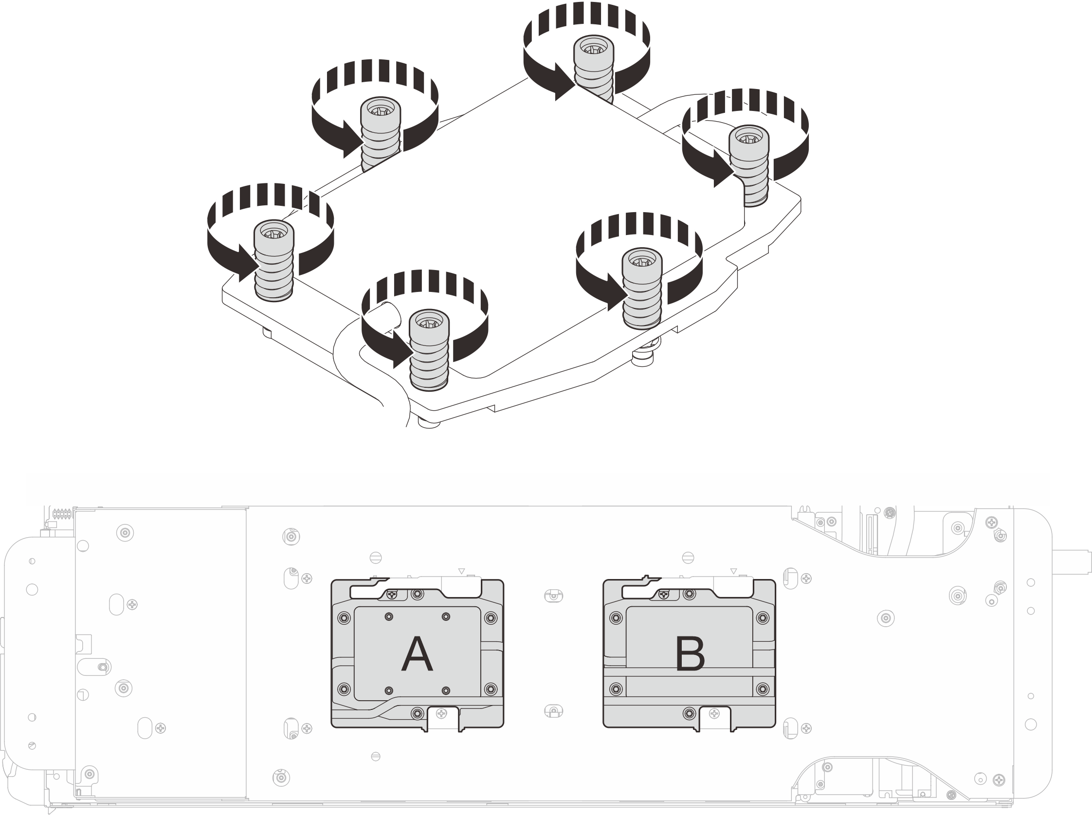
- Install processor cold plate screws (x12 Torx T20 screws for the CPU node). Follow the screw sequence specified below and tighten the screws with a torque screwdriver. Fully tighten each screw; then, proceed to the next screw.NoteFor reference, the torque required for the screws to be fully tightened/removed is 1.12-1.46 newton-meters, 10-13 inch-poundsFigure 8. Processor cold plate installationFully tighten each screw the order below:
Processor Screw sequence A B 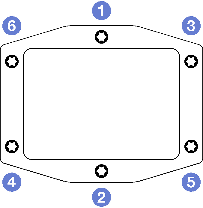
- Loosen water loop carrier screws (12x Phillips #2 screws).NoteSelect screw holes marked as
R on the rear of the shipping bracket. Figure 9. Loosening water loop carrier screws
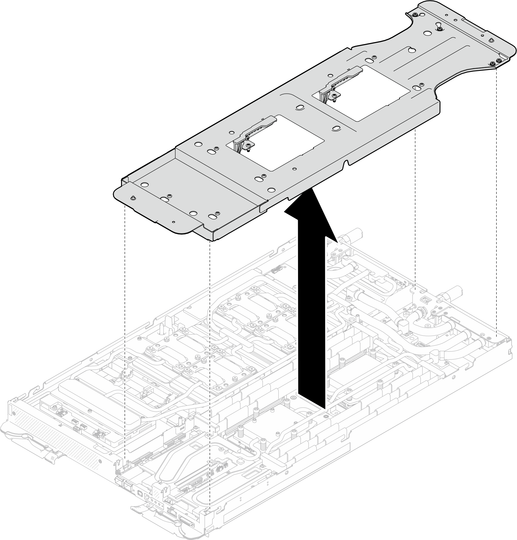
- Remove the water loop carrier from the compute node.Figure 10. Water loop carrier removal (Compute node)
- Install water loop screws and quick connect screws (14x Torx T10 screws per node) with a torque screwdriver set to the proper torque.Note
For reference, the torque required for the screws to be fully tightened/removed is 5.0+/- 0.5 lbf-in, 0.55+/- 0.05 N-M.
Install the 1 VR cold plate screws (x2) with washers. Use the washers previously removed from the water loop.
Figure 11. VR cold plate screws with washer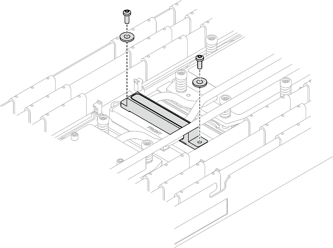 Figure 12. Water loop screws and quick connect screws installation
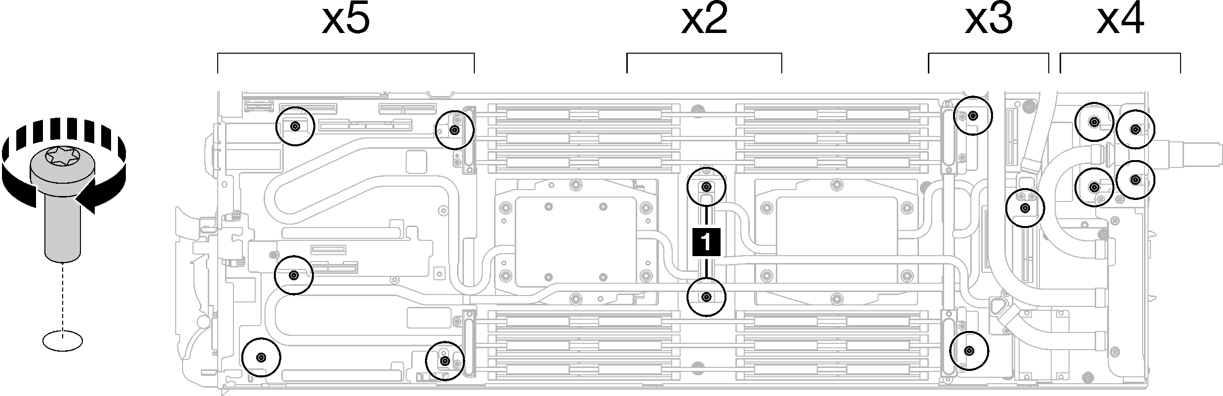
- Install the five Torx T10 screws to secure the quick connect.NoteFor reference, the torque required for the screws to be fully tightened/removed is 5.0+/- 0.5 lbf-in, 0.55+/- 0.05 N-M.Figure 13. Quick connect screw installation (Compute node)
- Replace the putty pads on the top side and the bottom side of the OSFP module conduction plate. AttentionPutty pad cannot be reused. Whenever a component is removed, putty pads must be replaced with new ones before reinstalling the component.Figure 14. OSFP module conduction plate putty pads replacement
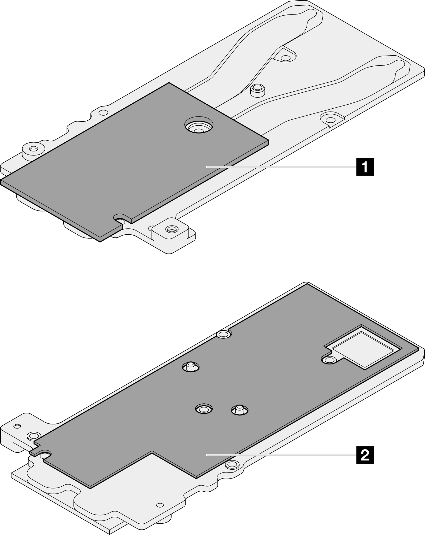
1 Conduction plate top putty pad
2 Conduction plate bottom putty pad
Make sure to follow Gap pad/putty pad replacement guidelines.
- Install the OSFP module conduction plate onto the water loop.
Screw Type Screwdriver Type 1 M3x5 screw (x3) Phillips #1 head screwdriver 2 M3 screw (x2) T10 screwdriver Figure 15. Installing the OSFP module conduction plate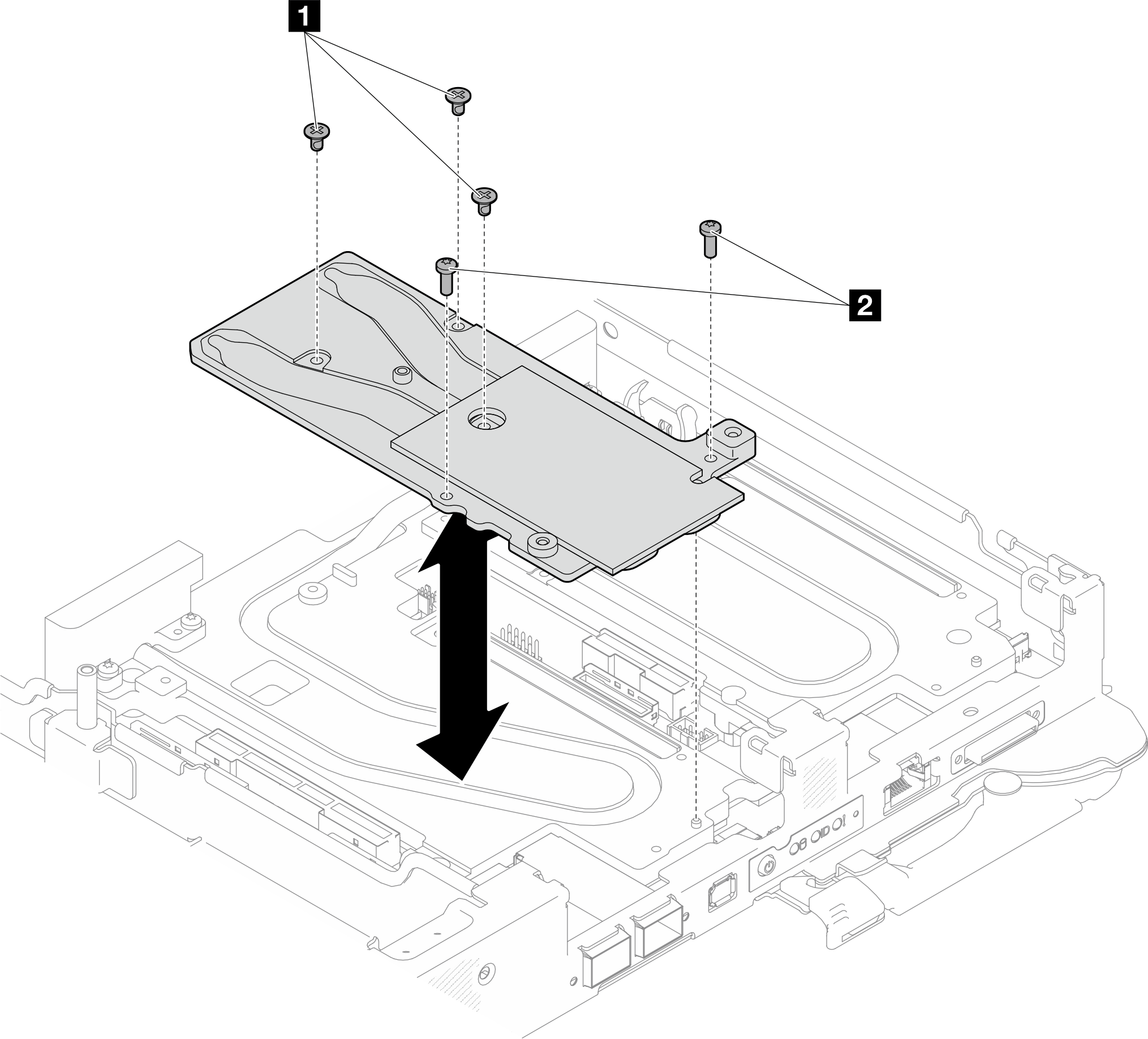
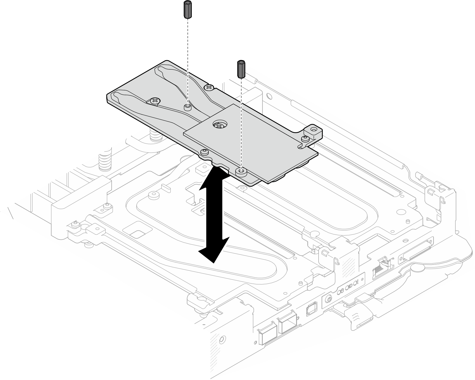
- Install the two Hex screws to the OSFP module with a 4.5 mm hex head screwdriver.Figure 16. OSFP module conduction plate Hex screws installation
Install the OSFP module. See Install the OSFP module.
Install the drive cage. See Install a drive cage assembly.
Install the MCIO cables. Follow the guidance and routing information in Internal cable routing.
Install the bus bar. See Install the bus bar.
Install the M.2 backplane assembly. See Install the M.2 backplane assembly.
Install the memory modules. See Install a memory module.
Install the DIMM comb. See Install a DIMM comb.
Install the cross braces. See Install the cross braces.
Install the tray cover. See Install the tray cover.
Install the tray into the enclosure. See Install a DWC tray in the enclosure.
- Connect all required external cables to the solution.NoteUse extra force to connect QSFP cables to the solution.
Check the power LED on each node to make sure it changes from fast blink to slow blink to indicate all nodes are ready to be powered on.
Demo video