Remove the 2.5-inch drive backplane
Use this information to remove the 2.5-inch drive backplane.
Read Installation Guidelines to ensure that you work safely.
- Carefully lay the compute node on a flat, static-protective surface, orienting the compute node with the bezel pointing toward you.
Remove the compute node cover (see Remove the compute node cover for instructions).
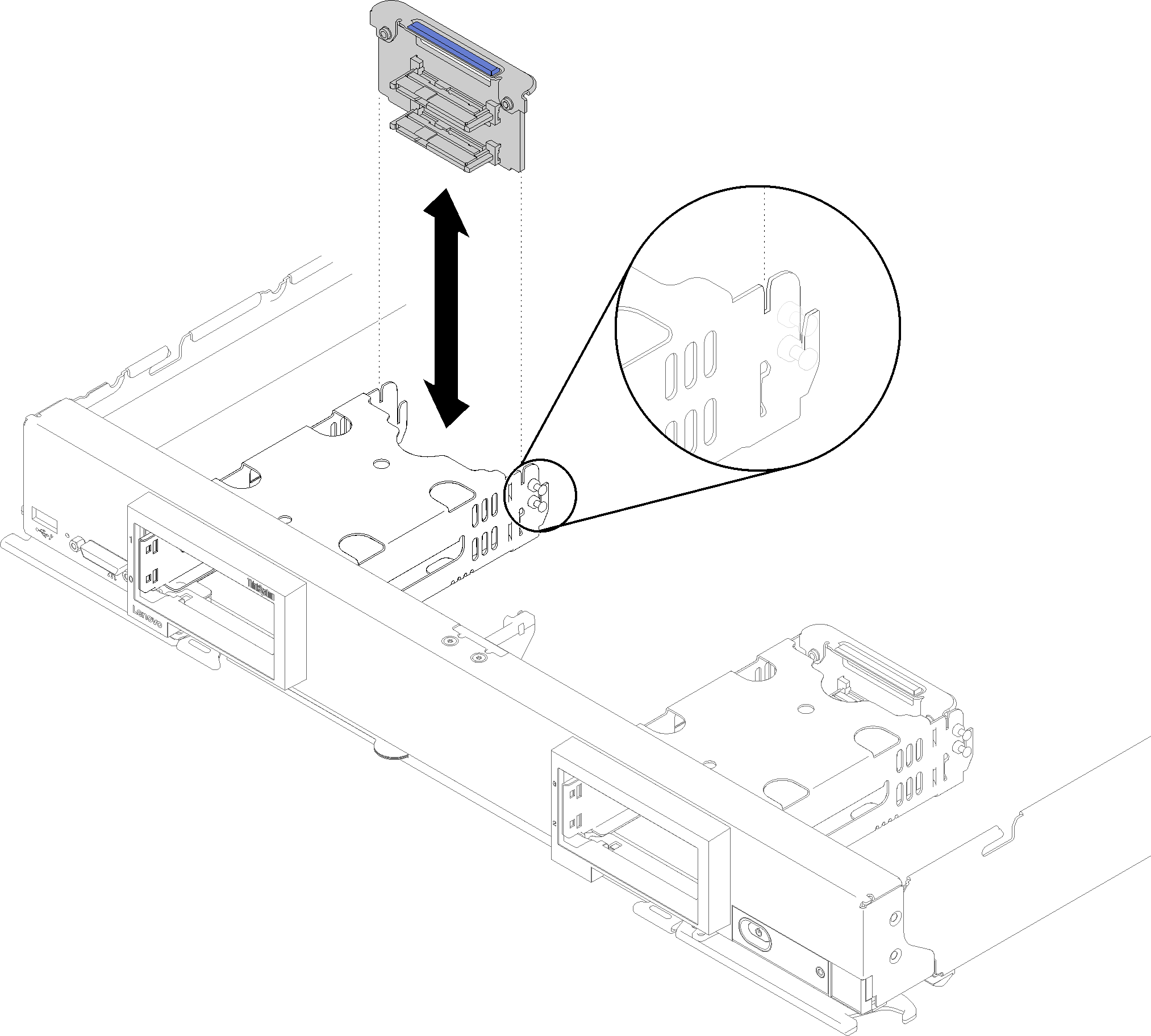
Several different types of 2.5-inch drive backplanes can be installed in the compute node. For example, some 2.5-inch drive backplanes come with a lever, while others don’t (please refer to the illustrations below). All are removed and installed in a similar manner.
See the documentation that comes with an optional drive backplane for device-specific information and information about removing other components that might be included as part of the option.
If necessary, remove the RAID adapter to more easily access the drive backplane (see Remove the RAID adapter).
To remove a 2.5-inch drive backplane, complete the following steps:
- Remove any drive bay fillers; then, press the release latch and pull out the drives to disengage the drive connectors from the backplane. There is no need to remove the drives completely.
- Lift the drive backplane out of the compute node.
If you are instructed to return the component or optional device, follow all packaging instructions, and use any packaging materials for shipping that are supplied to you.
Demo video