4 x 3.5'' AnyBay backplane
Use this section to understand the AnyBay backplane cable routing for server model with four 3.5-inch front drives.
To connect cables for a 7mm drive backplane, refer to 7mm drive backplane.
To connect power cables for a backplane for standard 2.5-inch or 3.5-inch drives, refer to Cable routing for backplane power.
To connect cables for M.2 drives, refer to M.2 drive backplane.
To connect signal cables for a backplane for standard 4 x 3.5-inch front drives, refer to the following cable routing scenarios depending on your server configuration:
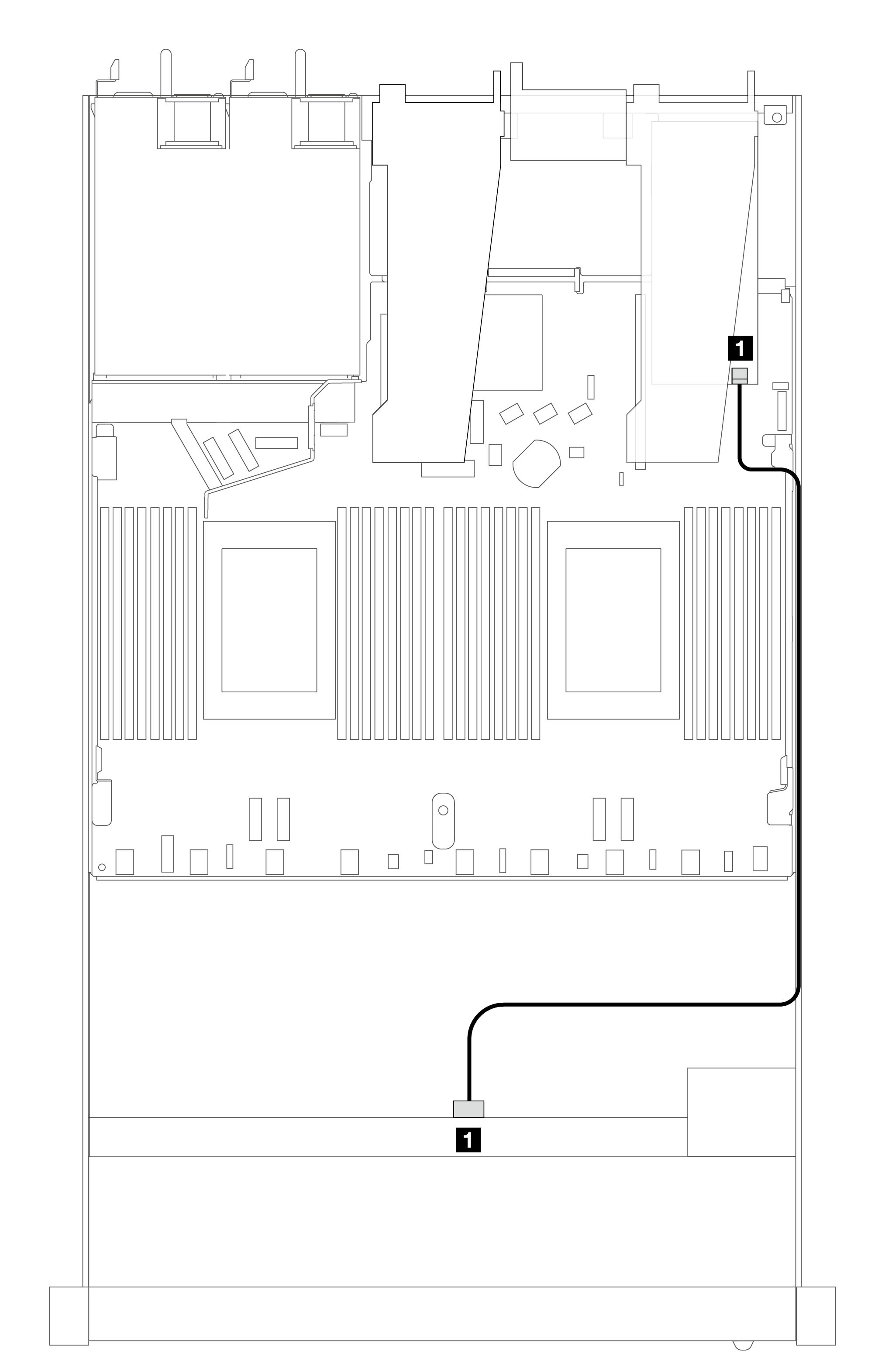
Cable routing for onboard configuration
The following table shows the mapping relationship between backplane connectors and processor board connectors for onboard configuration.
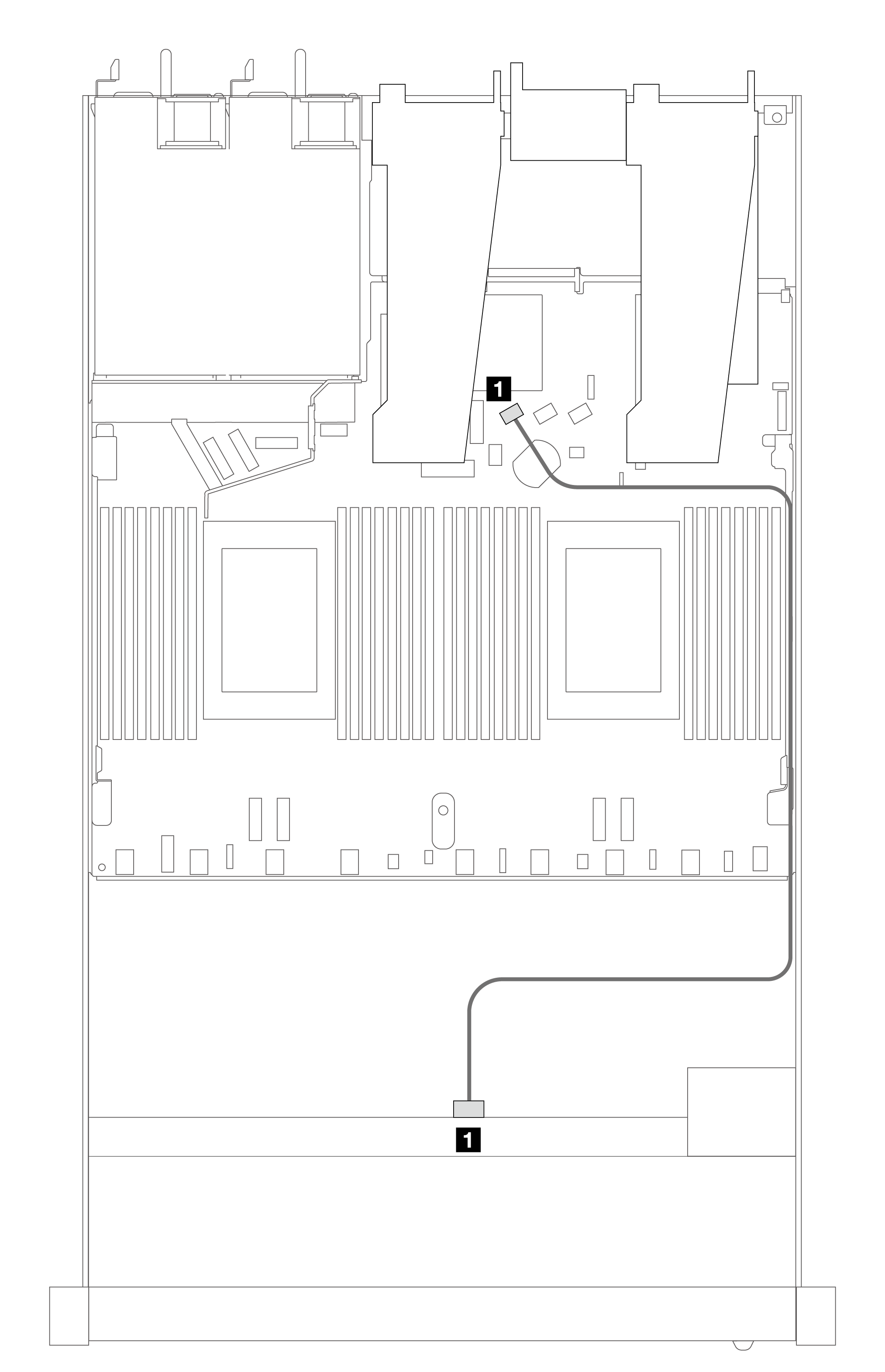 |  | ||||
| SAS/SATA cable routing | NVMe cable routing | ||||
| SAS/SATA connector | From | To | NVMe connector | From | To |
| 1 SAS | Front BP | SATA 0 | 1 2–3, 0–1 | Front BP | PCIe 1, PCIe 2 |
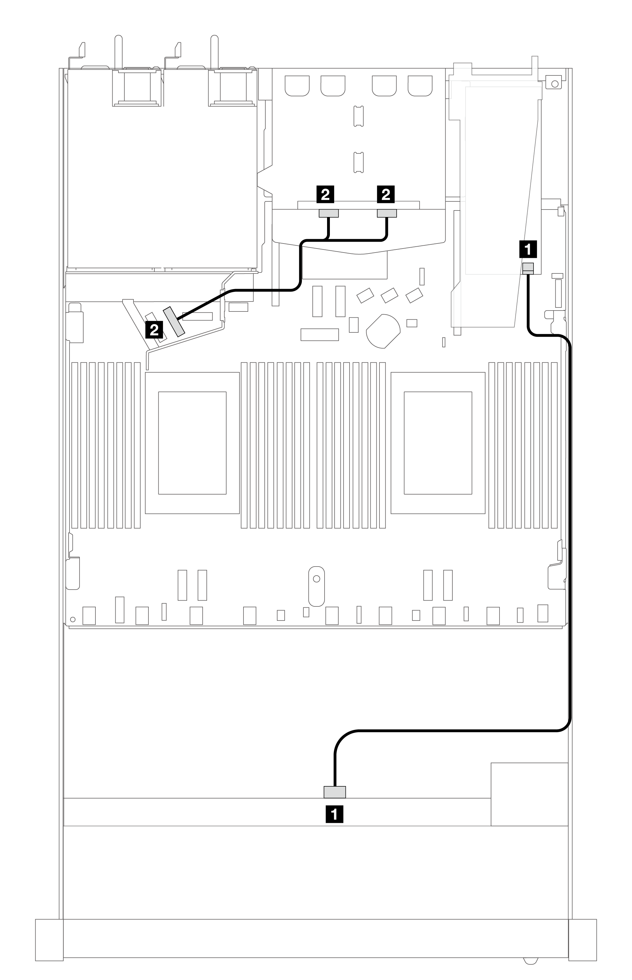
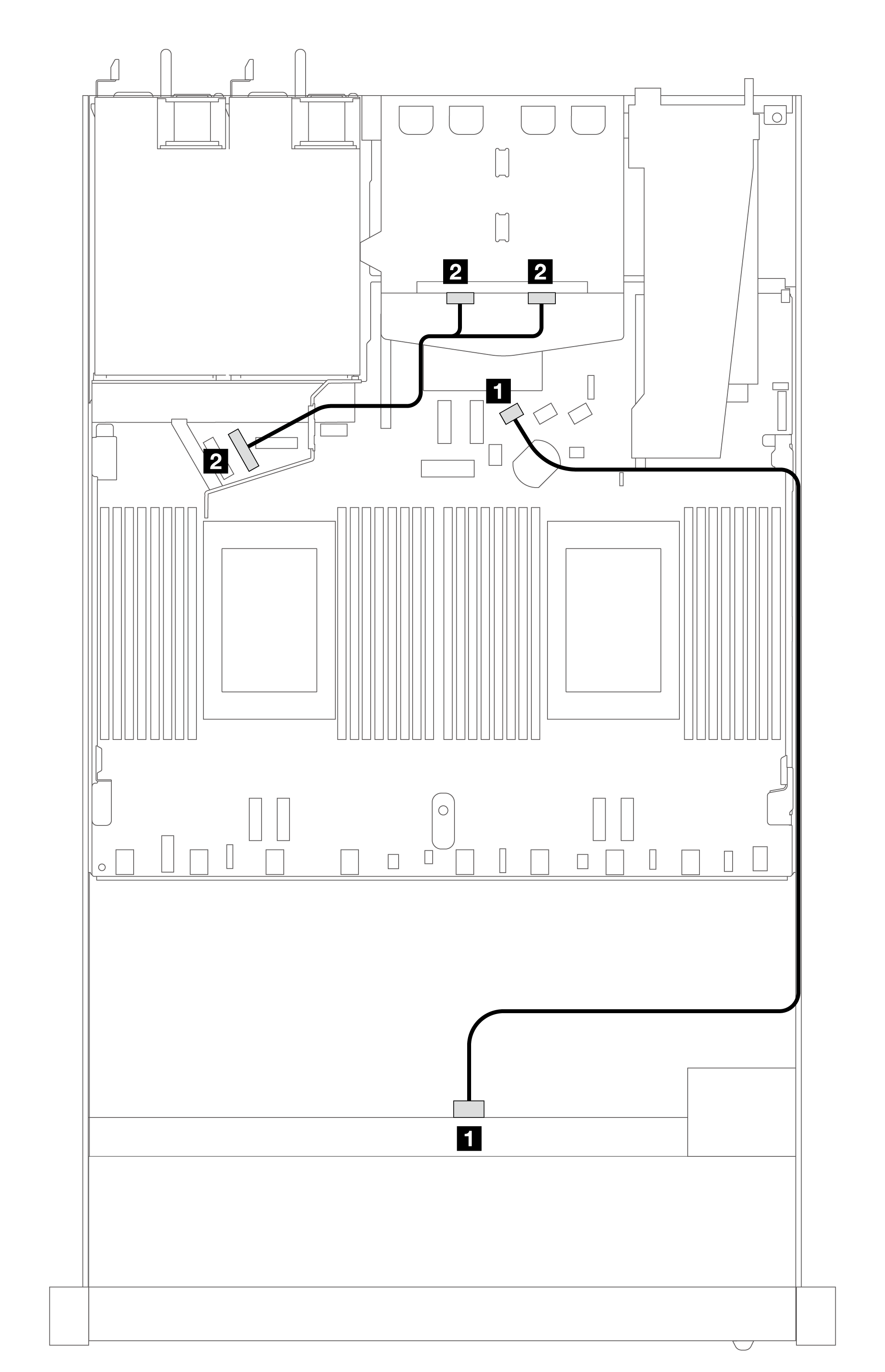 | | ||||
| Connector | From | To | NVMe cable routing | ||
| 1 SAS | Front BP | SATA 0 | NVMe connector | From | To |
| 2 NVMe | Rear BP | PCIe 6 | 1 2–3, 0–1 | Front BP | PCIe 1, PCIe 2 |
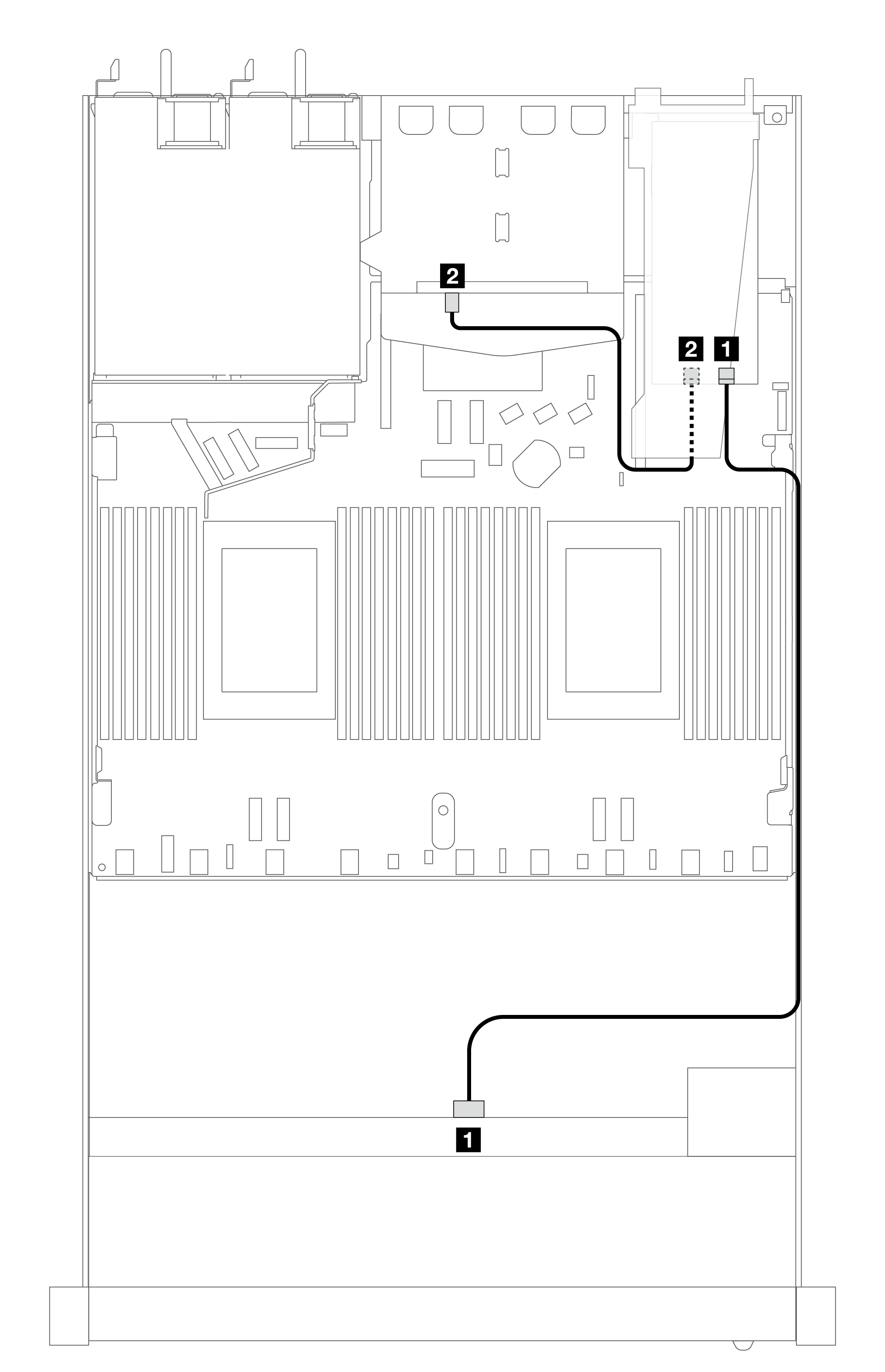
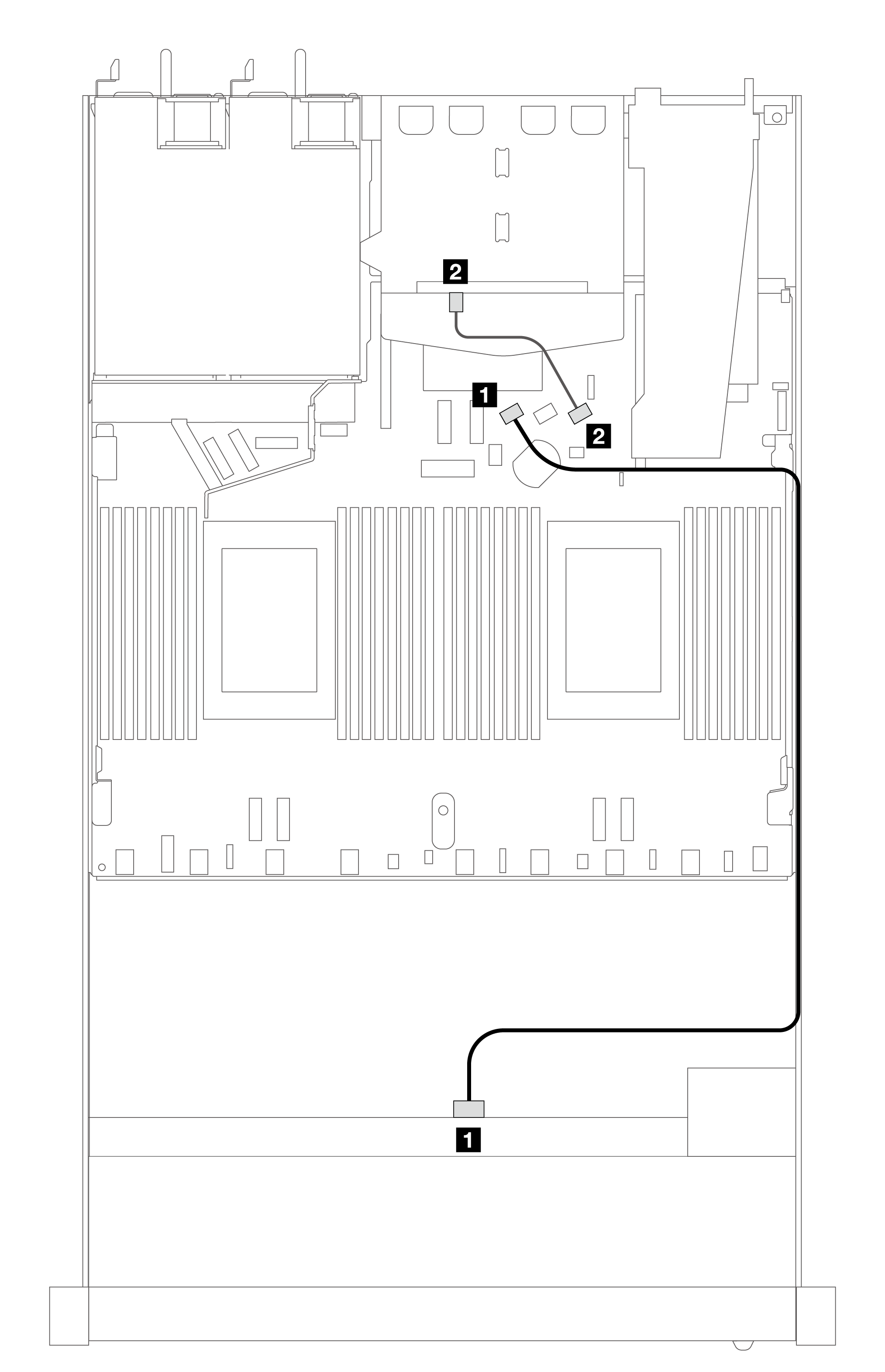 | | ||||
| SAS/SATA cable routing | NVMe cable routing | ||||
| 1 SAS | Front BP | SATA 0 | NVMe connector | From | To |
| 2 SAS | Rear BP | SATA 2 | 1 2–3, 0–1 | Front BP | PCIe 1, PCIe 2 |
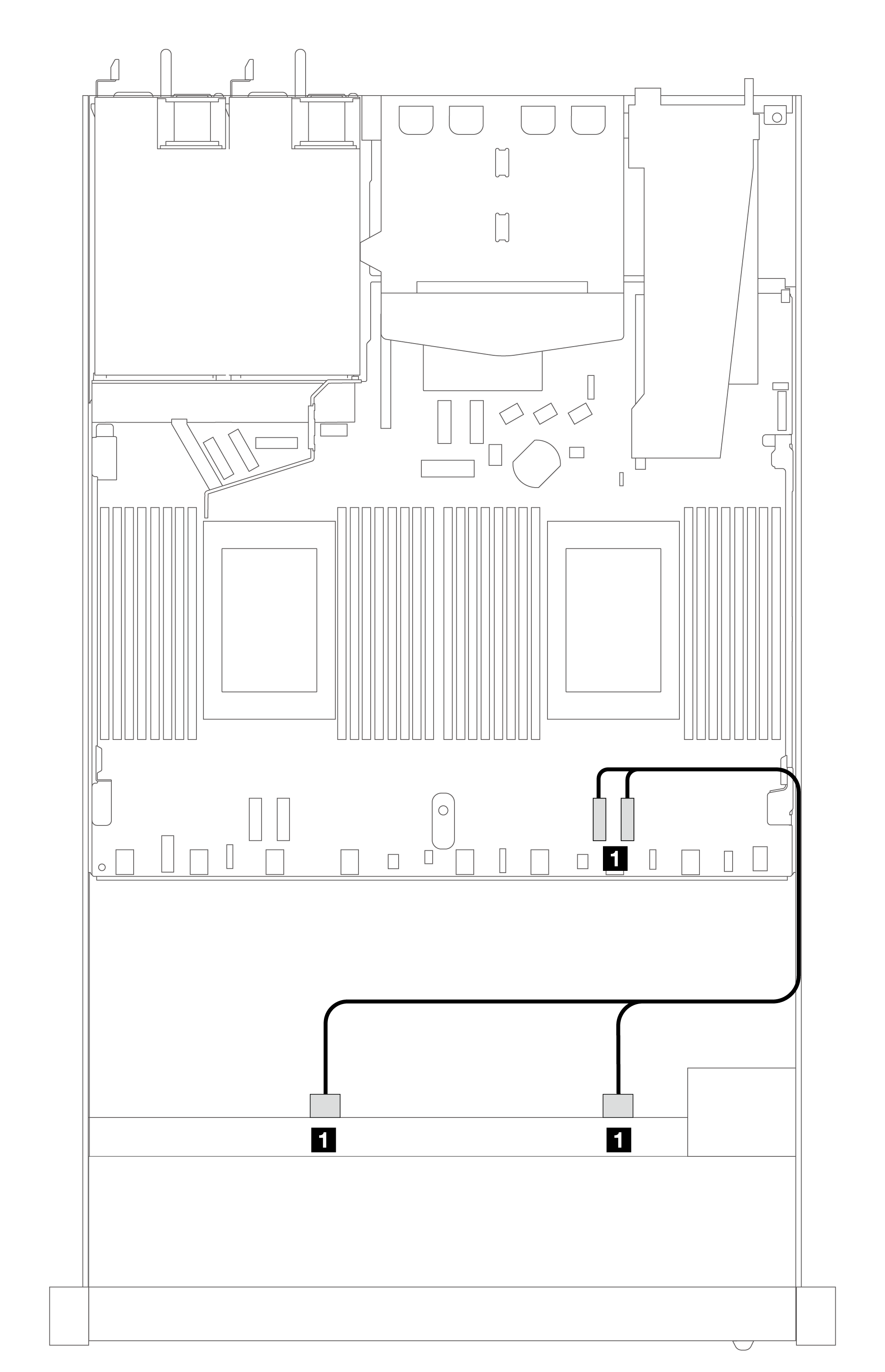
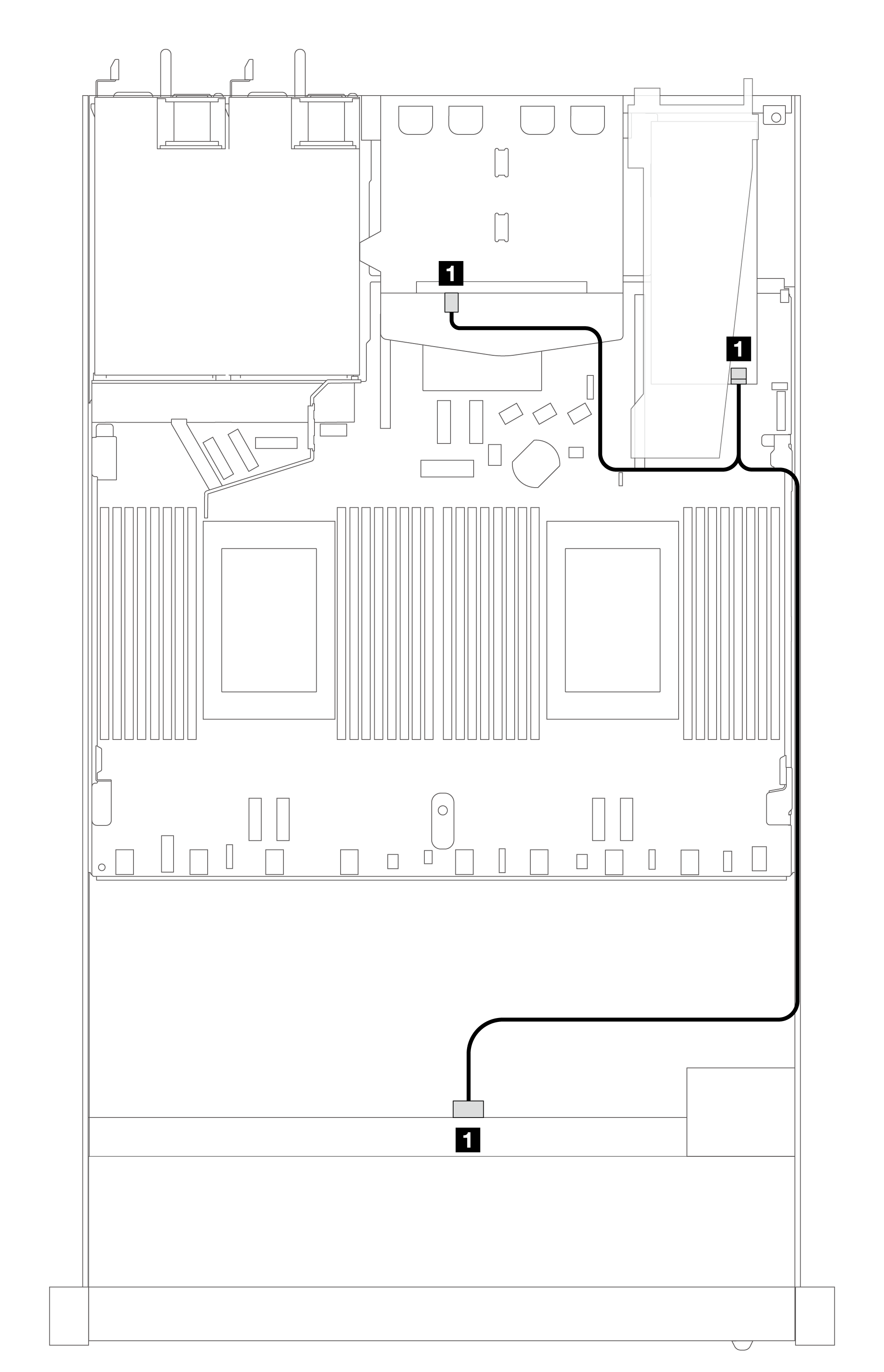
Cable routing with an SFF HBA/RAID adapter
The following table shows the mapping relationship between backplane connectors and processor board/adapter connectors when an 8i SFF HBA/RAID adapter (Gen 3 or Gen 4) is installed.
 | | ||||
| SAS/SATA cable routing | NVMe cable routing | ||||
| SAS/SATA connector | From | To | NVMe connector | From | To |
| 1 SAS | Front BP | C0 | 1 2–3, 0–1 | Front BP | PCIe 1, PCIe 2 |
Note
Gen 3 and Gen 4 SFF HBA/RAID adapters are slightly different in their connectors, but the cable routing method is similar.
 | | ||||
| Connector | From | To | NVMe cable routing | ||
| 1 SAS | Front BP | C0 | NVMe connector | From | To |
| 2 NVMe | Rear BP | PCIe 6 | 1 2–3, 0–1 | Front BP | PCIe 1, PCIe 2 |
 | | ||||
| Connector | From | To | NVMe cable routing | ||
| 1 SAS | Front BP | C0 | NVMe connector | From | To |
| 2 SAS | Rear BP | C1 | 1 2–3, 0–1 | Front BP | PCIe 1, PCIe 2 |
 | | ||||
| SAS/SATA cable routing | NVMe cable routing | ||||
| SAS/SATA connector | From | To | NVMe connector | From | To |
| 1 SAS | Front and rear BP | C0 | 1 2–3, 0–1 | Front BP | PCIe 1, PCIe 2 |
Give documentation feedback