8 x 2.5'' AnyBay drives with 10 x 2.5'' AnyBay backplane (one processor)
Use this section to understand the cable routing for eight AnyBay drives with 10 x 2.5 Anybay backplane and one processor installed.
To connect cables for a 7mm drive backplane, refer to 7mm drive backplane.
To connect power cables for a backplane for standard 2.5-inch or 3.5-inch drives, refer to Cable routing for backplane power.
The following illustration and table show the cabling among the front backplane, the processor board and a Gen 4 SFF re-timer adapter.
Figure 1. Cable routing of eight AnyBay front drives for both connections onboard and to a Gen 4 SFF re-timer adapter
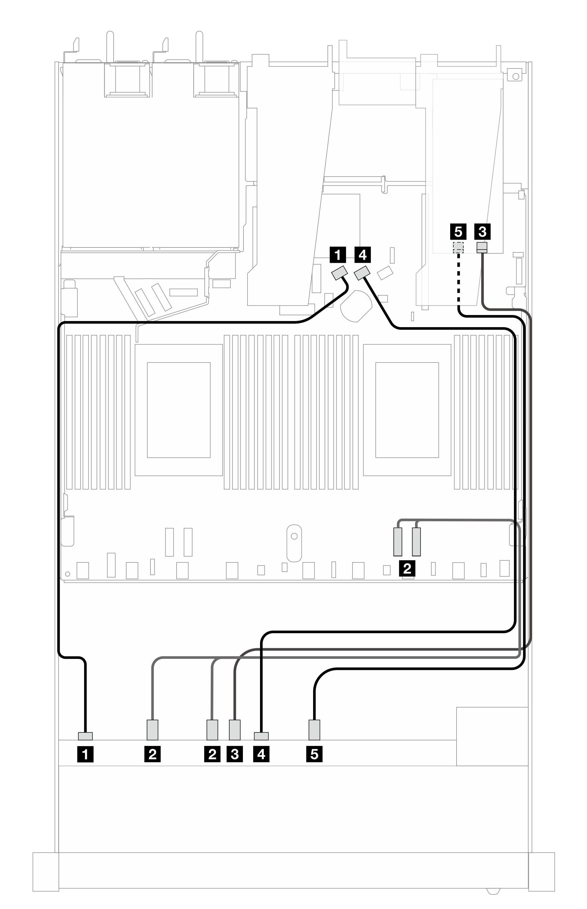
| Backplane | From | To |
|---|---|---|
| Front BP (SAS) | 1 SAS 0 | 1 SATA 0 |
| Front BP (NVMe) | 2 NVMe 0–1, 2–3 | 2 PCIe 2, PCIe 1 |
| 3 NVMe 4–5 | 3 C0 | |
| Front BP (SAS) | 4 SAS 1 | 4 SATA 1 |
| Front BP (NVMe) | 5 NVMe 6–7 | 5 C1 |
Give documentation feedback