4 x 2.5'' front drives with front riser assembly (Gen 5 backplane)
Use the section to understand the cable routing for signal cable connections for 4 x 2.5'' front drives with the front riser assembly and 4 x 2.5'' Gen 5 AnyBay backplane installed.
To connect cables for a 7mm drive backplane, refer to 7mm drive backplane.
To connect power cables for a backplane for standard 2.5-inch or 3.5-inch drives, refer to Cable routing for backplane power.
To connect cables for the front riser assembly, refer to Front riser assembly.
To connect cables for the rear NVMe drives, refer to Rear NVMe drive backplane.
Cable routing for onboard configuration
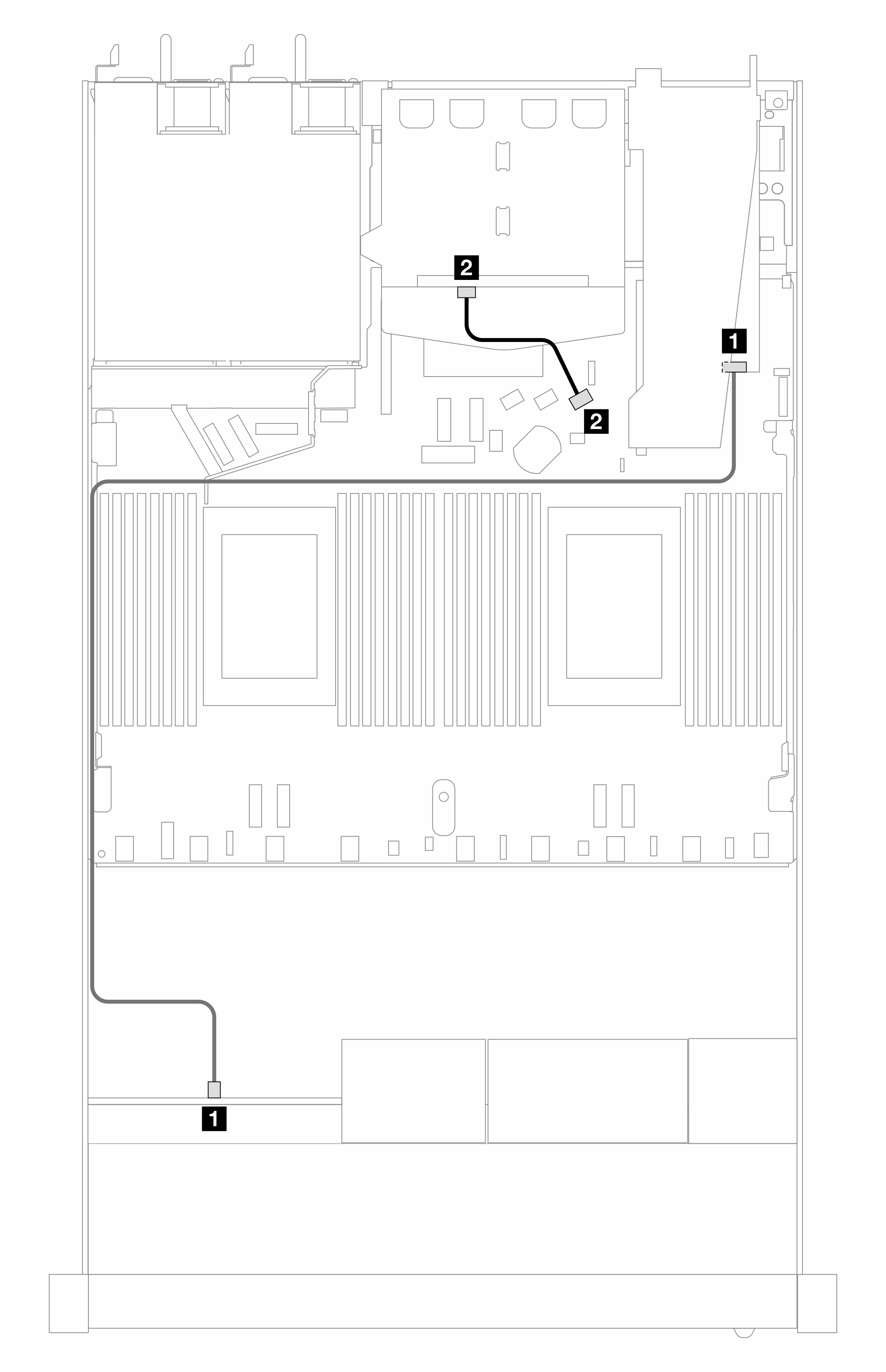
The following table shows the mapping relationship between backplane connectors and processor board connectors for onboard configuration.
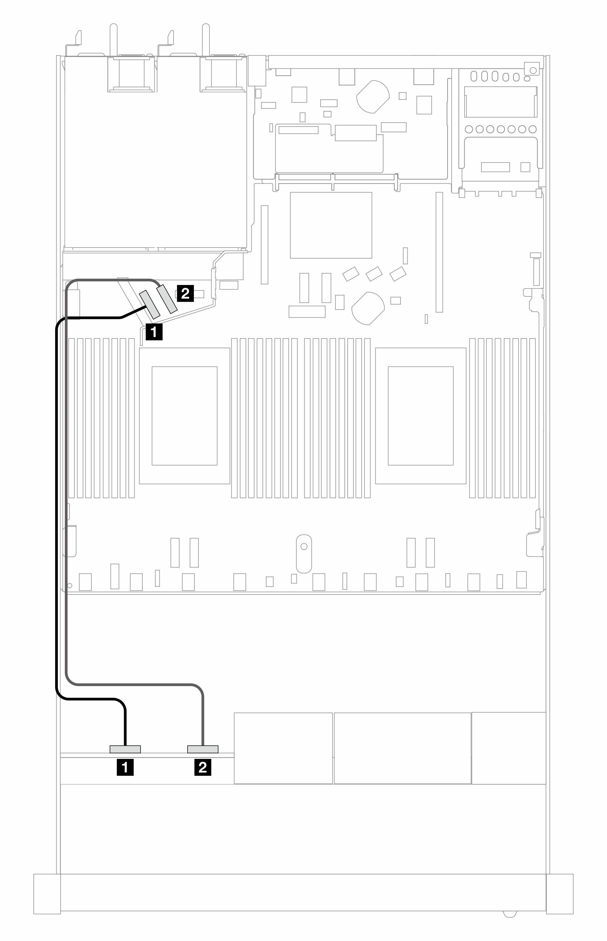
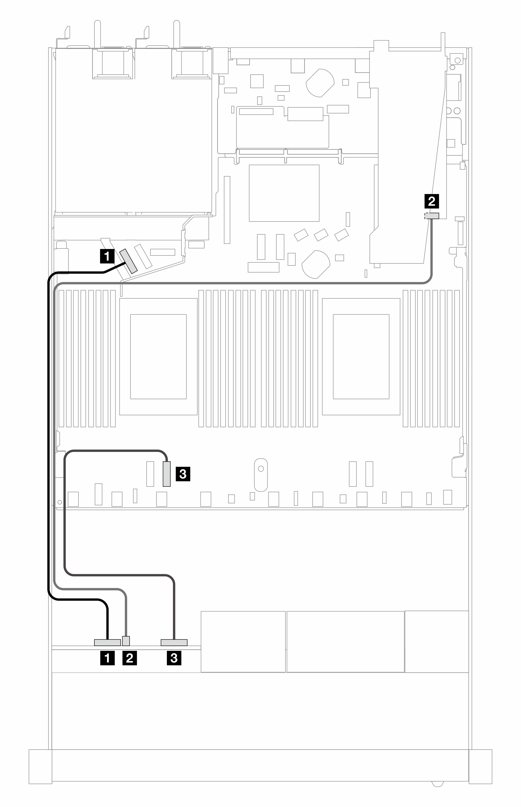
The following figure illustrates the cable routing for the onboard configuration of 4 x 2.5-inch front AnyBay drive bays. Connections between connectors: 1 ↔ 1, 2 ↔ 2, 3 ↔ 3, ... n ↔ n
| Backplanes | From | To |
|---|---|---|
| Front BP (NVMe) | 1 NVMe 0–1 | 1 PCIe 5 |
| 2 NVMe 2–3 | 2 PCIe 6 |
| Backplanes | From | To |
|---|---|---|
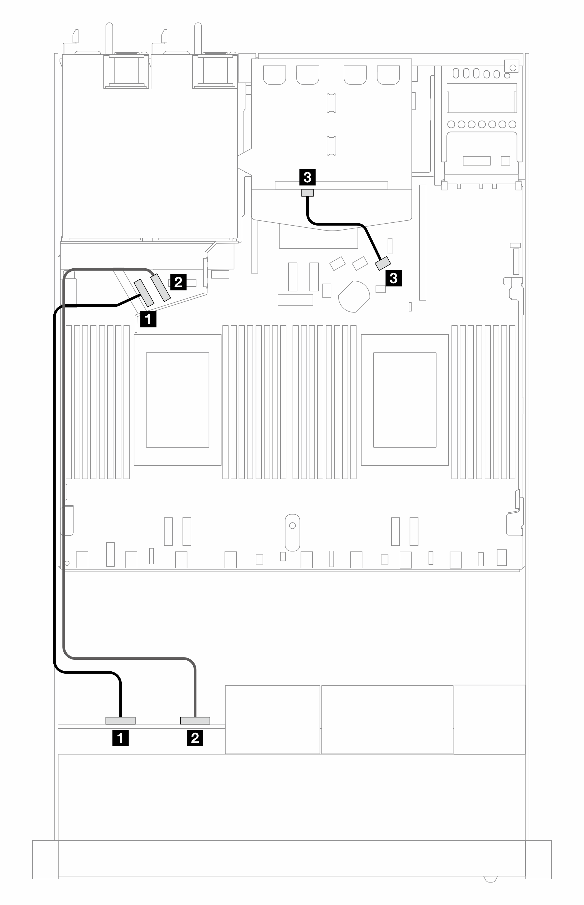
| Front BP (NVMe) | 1 NVMe 0–1 | 1 PCIe 5 |
| 2 NVMe 2–3 | 2 PCIe 6 | |
| Rear BP (SAS) | 3 SAS (rear) | 3 SATA 2 |
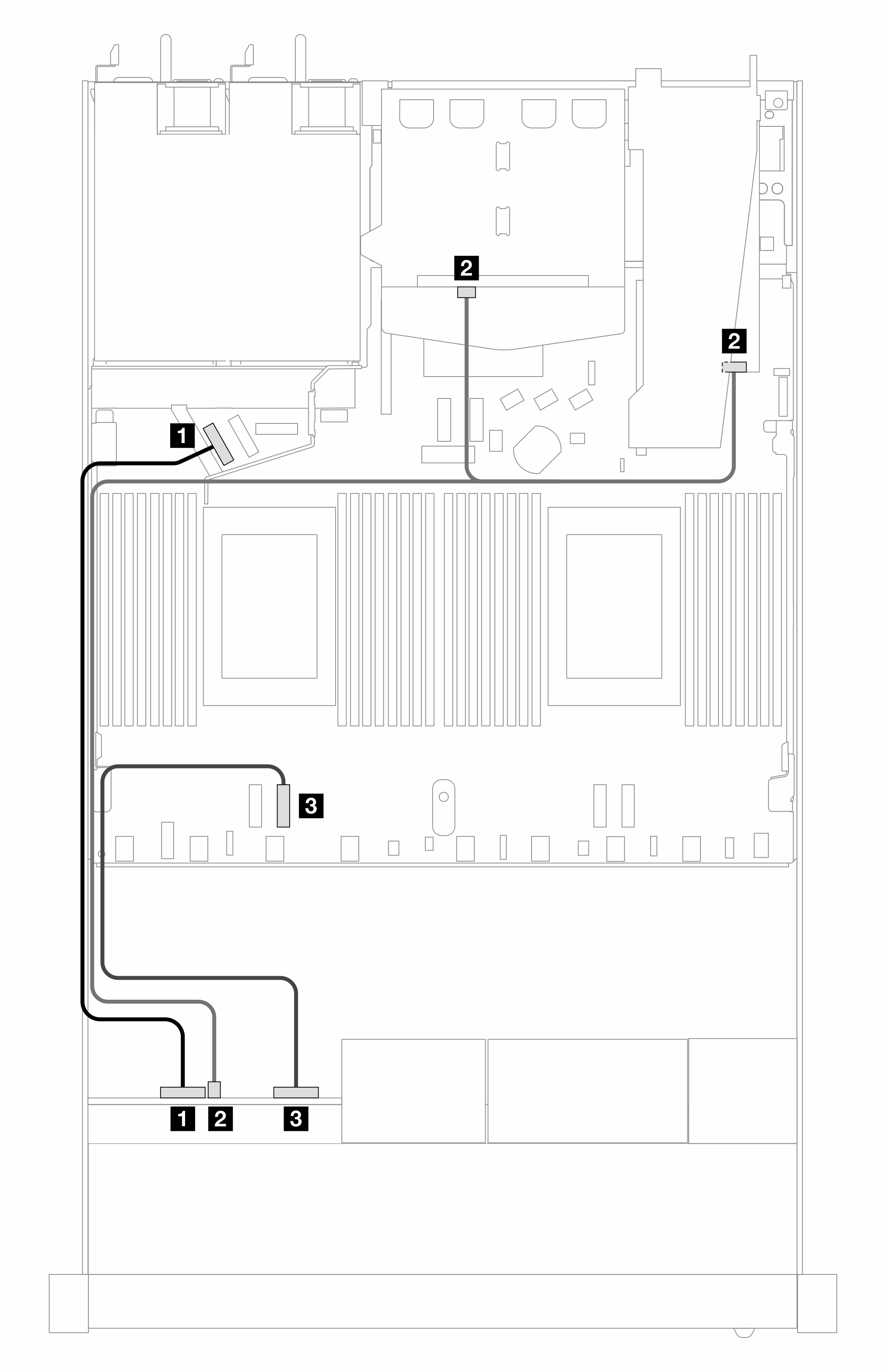
| Backplanes | From | To |
|---|---|---|
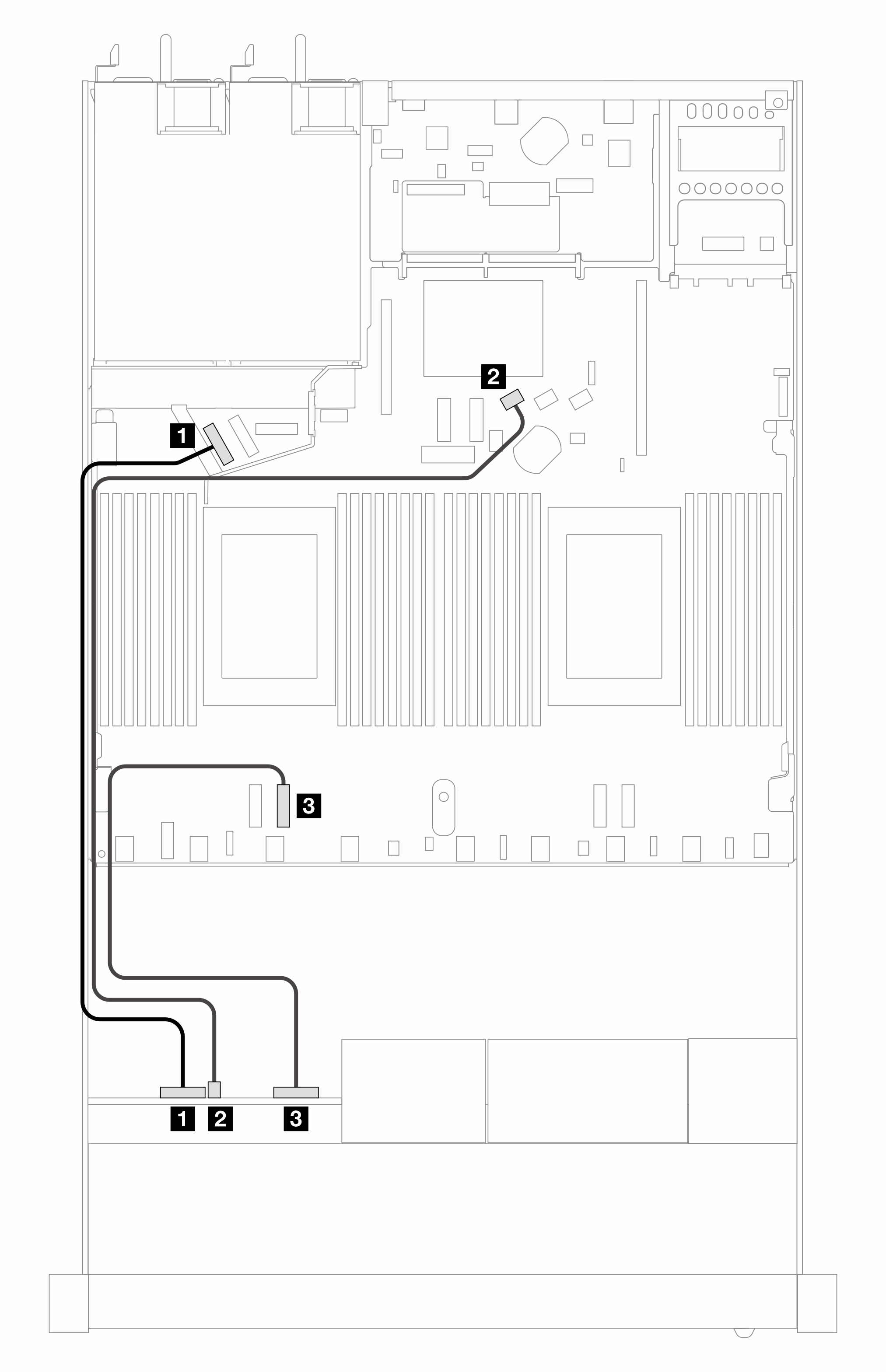
| Front BP (NVMe) | 1 NVMe 0–1 | 1 PCIe 5 |
| Front BP (SAS) | 2 SAS (front) | 2 SATA 0 |
| Front BP (NVMe) | 3 NVMe 2–3 | 3 PCIe 3 |
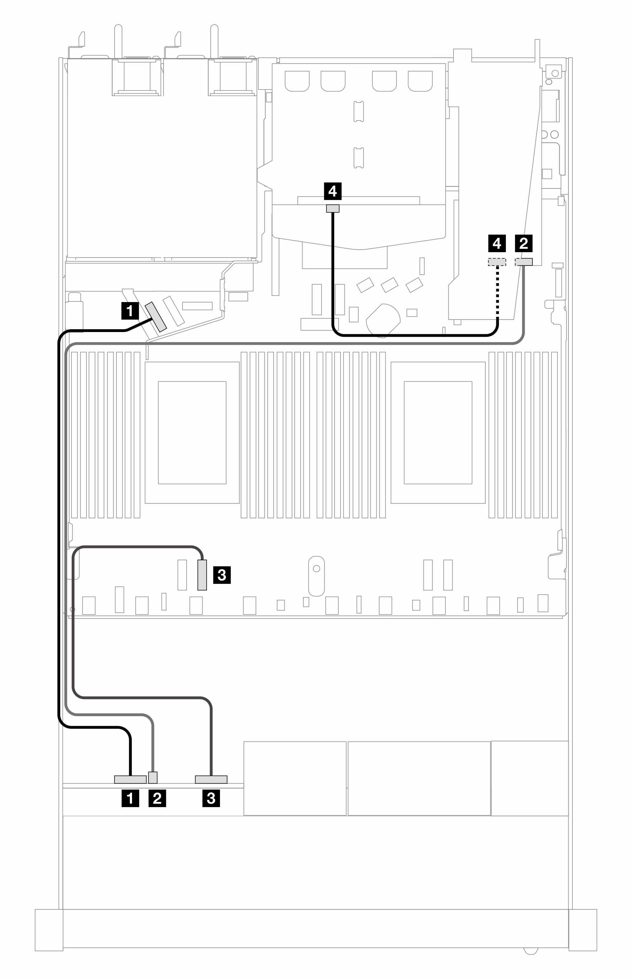
| Backplanes | From | To |
|---|---|---|
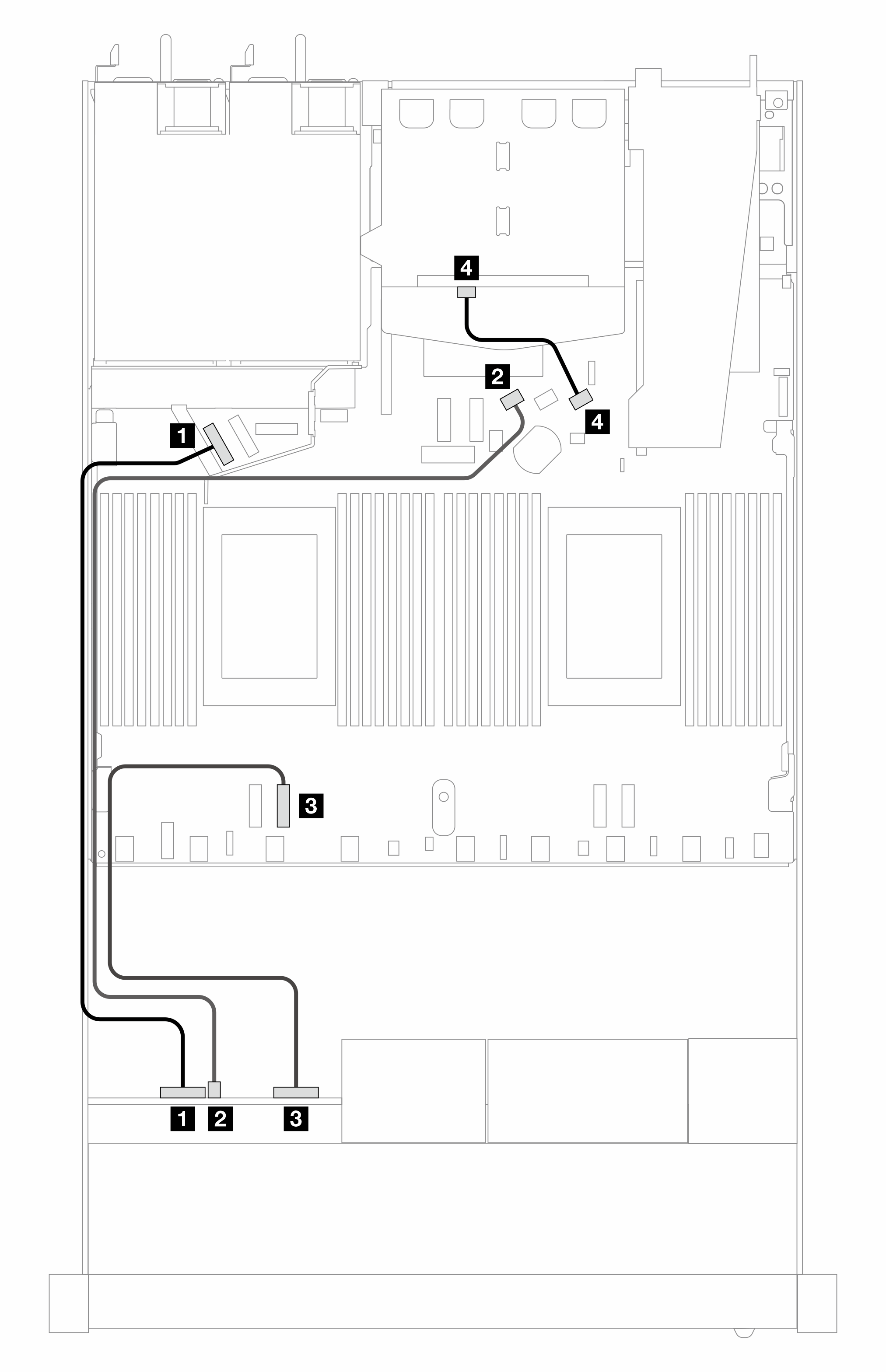
| Front BP (NVMe) | 1 NVMe 0–1 | 1 PCIe 5 |
| Front BP (SAS) | 2 SAS (front) | 2 SATA 0 |
| Front BP (NVMe) | 3 NVMe 2–3 | 3 PCIe 3 |
| Rear BP (SAS) | 4 SAS (rear) | 4 SATA 2 |
Cable routing with an SFF HBA/RAID adapter
The following table shows the mapping relationship between backplane connectors and processor board/adapter connectors when an 8i SFF HBA/RAID adapter (Gen 3 or Gen 4) is installed.
The following figure illustrates the cable routing for the configuration of 4 x 2.5-inch front AnyBay drive bays with an 8i SFF RAID adapter. Connections between connectors: 1 ↔ 1, 2 ↔ 2, 3 ↔ 3, ... n ↔ n
| Backplanes | From | To |
|---|---|---|
| Front BP (NVMe) | 1 NVMe 0–1 | 1 PCIe 5 |
| Front BP (SAS) | 2 SAS (front) | 2 C0 |
| Front BP (NVMe) | 3 NVMe 2–3 | 3 PCIe 3 |
| Backplanes | From | To |
|---|---|---|
| Front BP (NVMe) | 1 NVMe 0–1 | 1 PCIe 5 |
| Front BP (SAS) | 2 SAS (front) | 2 C0 |
| Front BP (NVMe) | 3 NVMe 2–3 | 3 PCIe 3 |
| Rear BP (SAS) | 4 SAS (rear) | 4 C1 |
| Backplanes | From | To |
|---|---|---|
| Front BP (NVMe) | 1 NVMe 0–1 | 1 PCIe 5 |
| Front and rear BP (SAS) | 2 SAS (front and rear) | 2 C0 |
| Front BP (NVMe) | 3 NVMe 2–3 | 3 PCIe 3 |
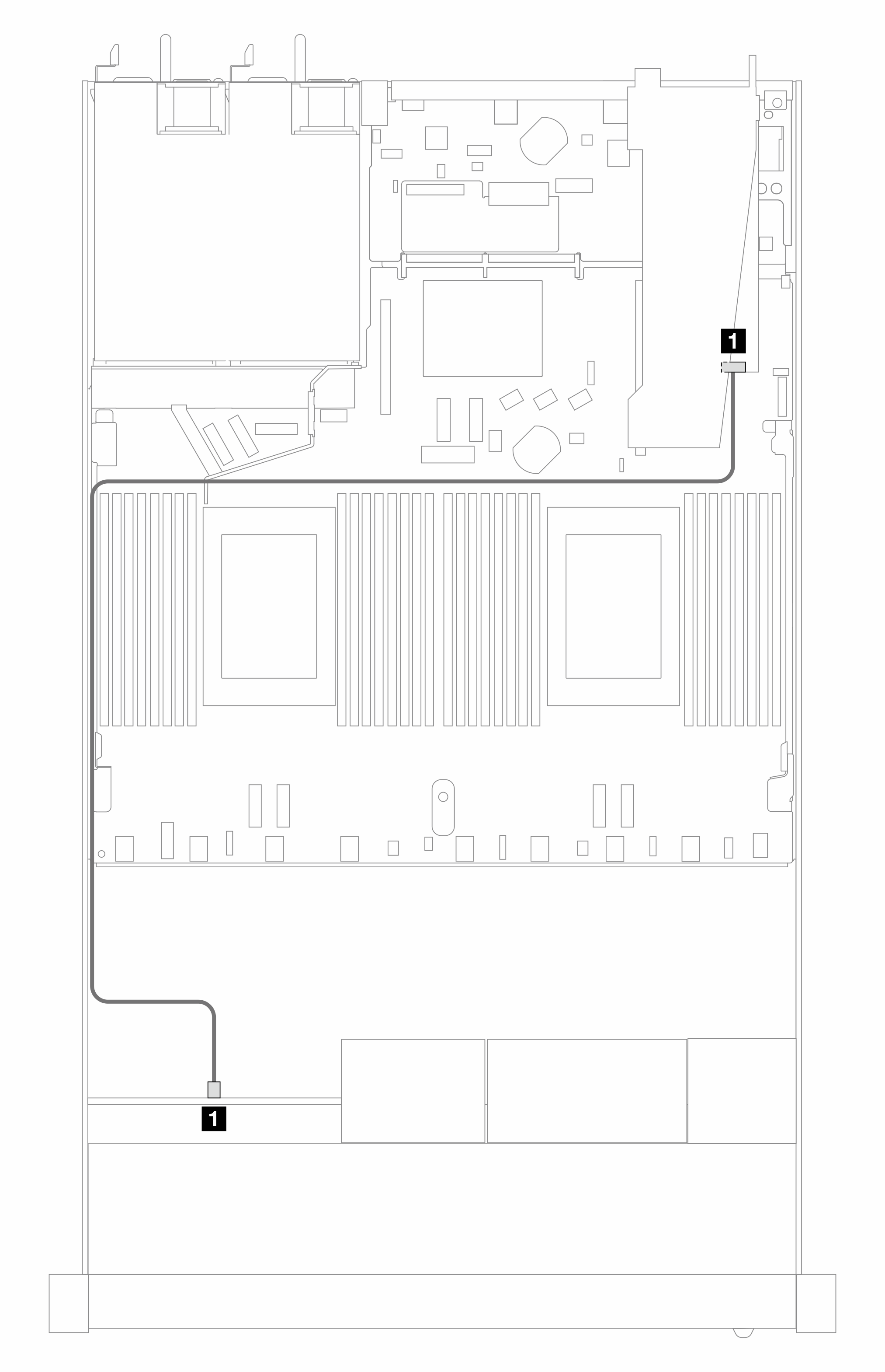
| Backplanes | From | To |
|---|---|---|
| Front BP (SAS) | 2 SAS (front) | 2 C0 |
| Backplanes | From | To |
|---|---|---|
| Front BP (SAS) | 1 SAS (front) | 1 C0 |
| Rear BP (SAS) | 2 SAS (rear) | 2 C1 |