E3.S backplane 4
See this section to understand the cable routing of E3.S backplane 4.
Figure 1. Cable routing for onboard configuration of E3.S backplane 4 (standard and liquid cooling configuration)
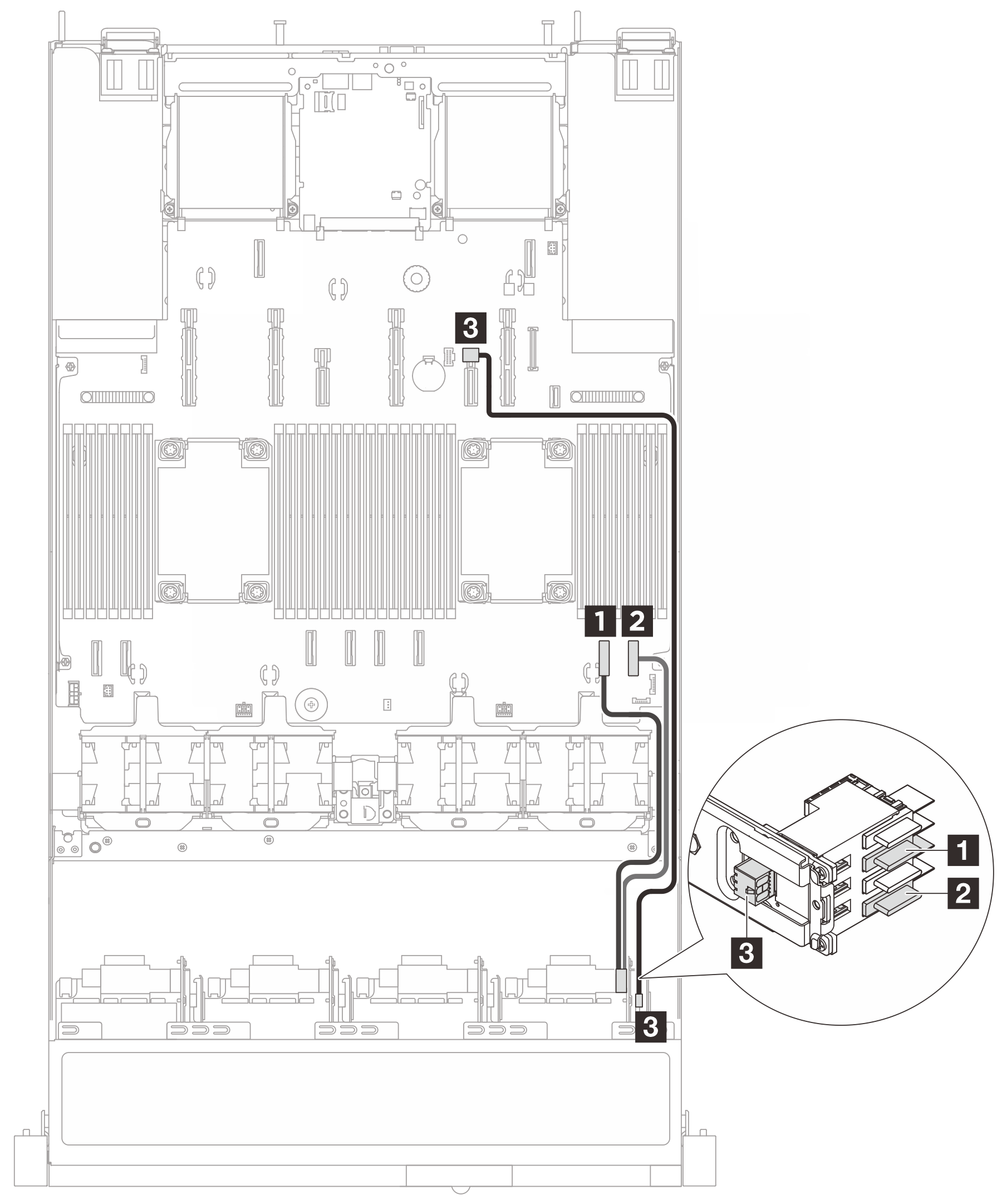
| From | To | Cable length |
|---|---|---|
1
| 1 PCIe connector 2 | 300 mm |
2
| 2 PCIe connector 1 | 300 mm |
| 3 Power connector | 3 Power connector 10 | 700 mm |
Figure 2. Cable routing for onboard configuration of E3.S backplane 4 (Compute Complex Neptune Core Module)
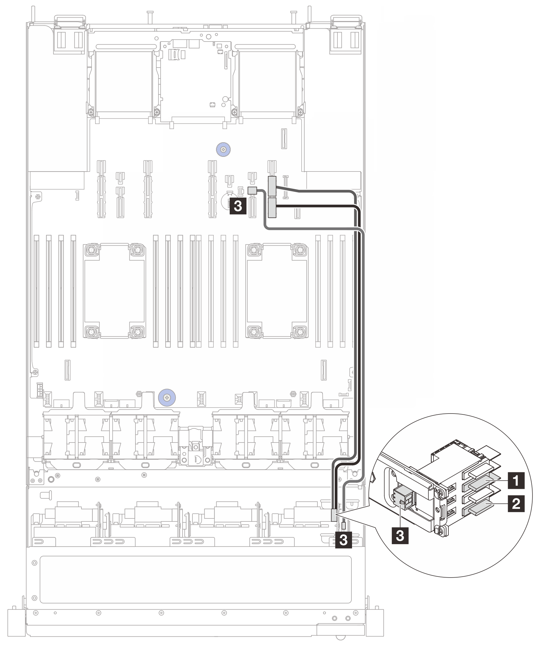
| From | To | Cable length |
|---|---|---|
| 1 Bay 0, Bay 1 (4X1T backplane) | 1 PCIe connector 9A | 630 mm |
| 2 Bay 2, Bay 3 (4X1T backplane) | 2 PCIe connector 9B | 630 mm |
| 3 Power connector | 3 Power connector 10 | 700 mm |
Give documentation feedback