4 x 2.5'' NVMe backplane
Use this section to understand the NVMe backplane cable routing for server model with four 2.5-inch front drives.
- For the locations of connectors on the processor board, refer to System-board-assembly connectors.
- To connect power cables for 2.5-inch drive backplanes, refer to Power/Sideband cable routing.
- To connect power and input cables for CFF RAID/HBA adapters, refer to CFF RAID/HBA adapter.
- To connect power and sideband cables for the rear drive backplane, refer to Rear NVMe/SATA drive backplane.
- To connect power and sideband cables for the 7mm drive backplane, refer to 7mm drive backplane.
- To connect cables for RAID flash power modules, refer to RAID flash power modules.
To connect signal cables for a backplane for standard 4 x 2.5-inch front drives, refer to the following cable routing scenarios depending on your server configuration:
Cable routing for onboard configuration
The following figure illustrates the cable routing for the onboard configuration of 4 x 2.5-inch front NVMe drive bays. Connections between connectors: 1 ↔ 1, 2 ↔ 2, 3 ↔ 3, ... n ↔ n
Figure 1. Cable routing for onboard configuration of 4 x 2.5-inch front NVMe drive bays (using 4 x2.5-inch AnyBay backplane (Gen 4))
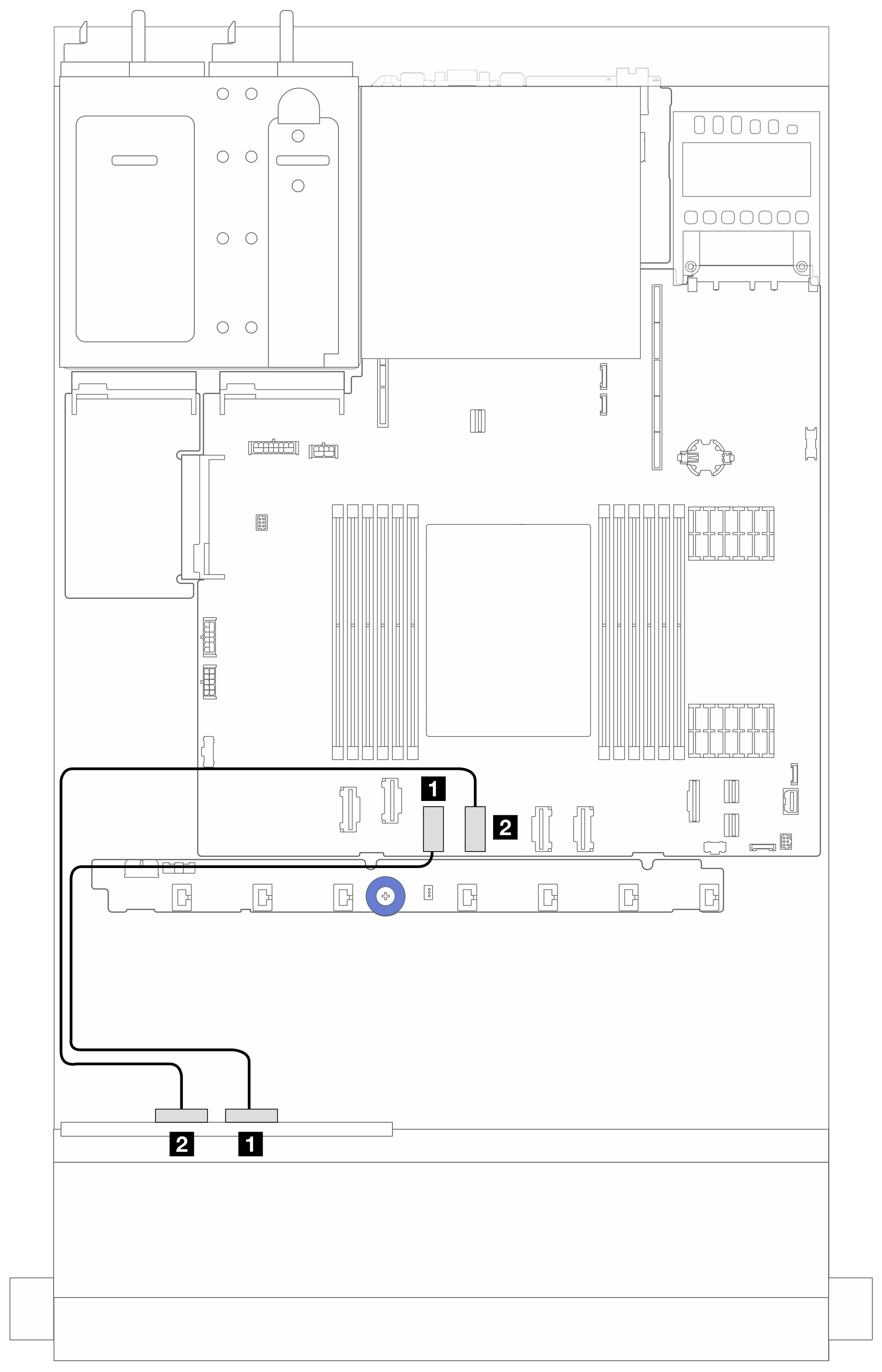
| From | To |
|---|---|
| 1 NVMe 2-3 on the front backplane | 1 PCIe connector 3 on the system board assembly |
| 2 NVMe 0-1 on the front backplane | 2 PCIe connector 4 on the system board assembly |
Figure 2. Cable routing for onboard configuration of 4 x 2.5-inch front NVMe drive bays (using 4 x2.5-inch AnyBay backplane (Gen 5))
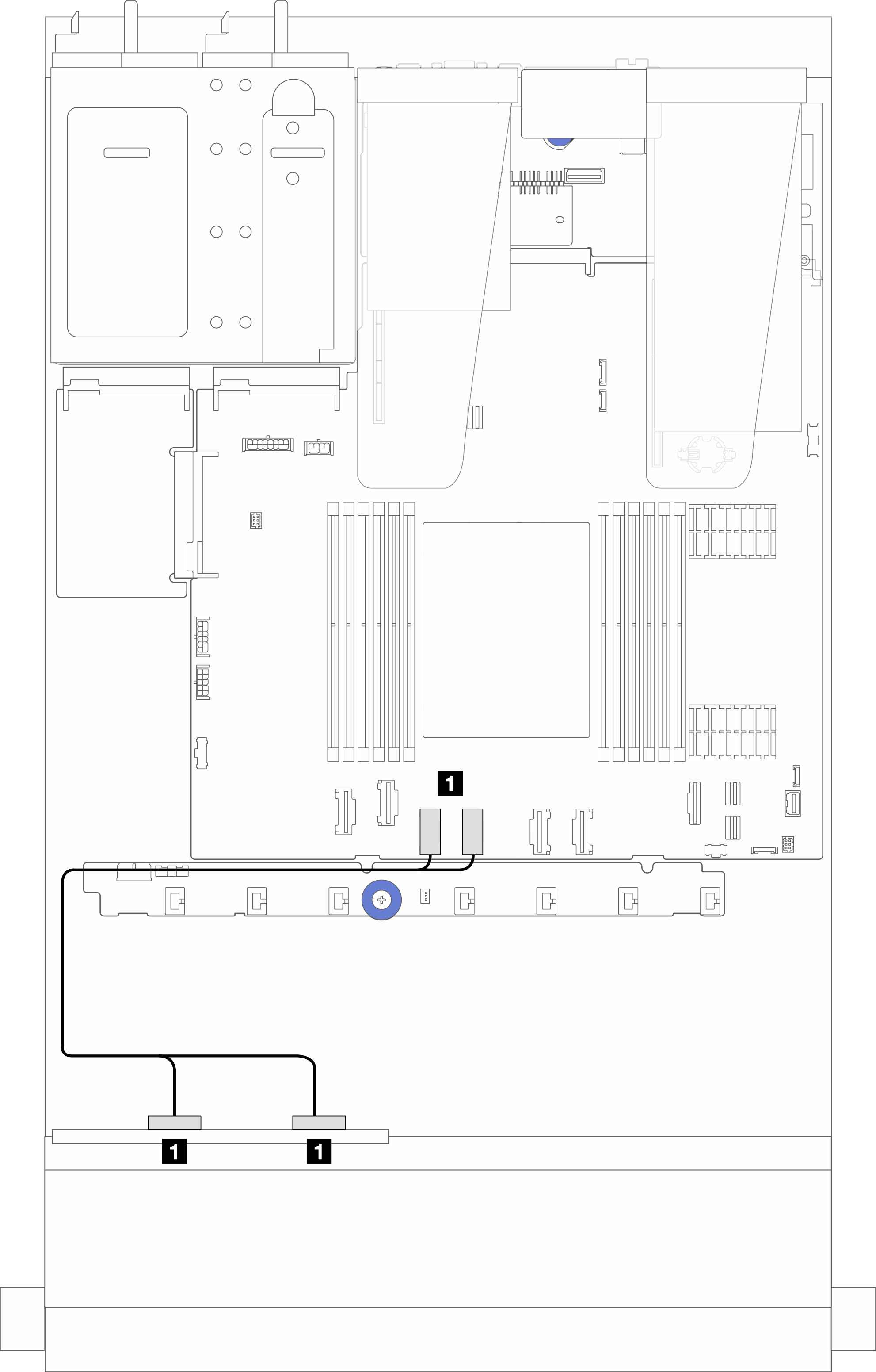
| From | To |
|---|---|
| 1 NVMe 2-3 and NVMe 0-1 on the front backplane | 1 PCIe connector 3 and 4 on the system board assembly |
Cable routing with an SFF RAID/HBA adapter
Figure 3. Cable routing of 4 x 2.5-inch front NVMe drive bays (using 4 x2.5-inch AnyBay backplane (Gen 5)) and an SFF 8i RAID/HBA adapter (Gen 3/Gen 4)
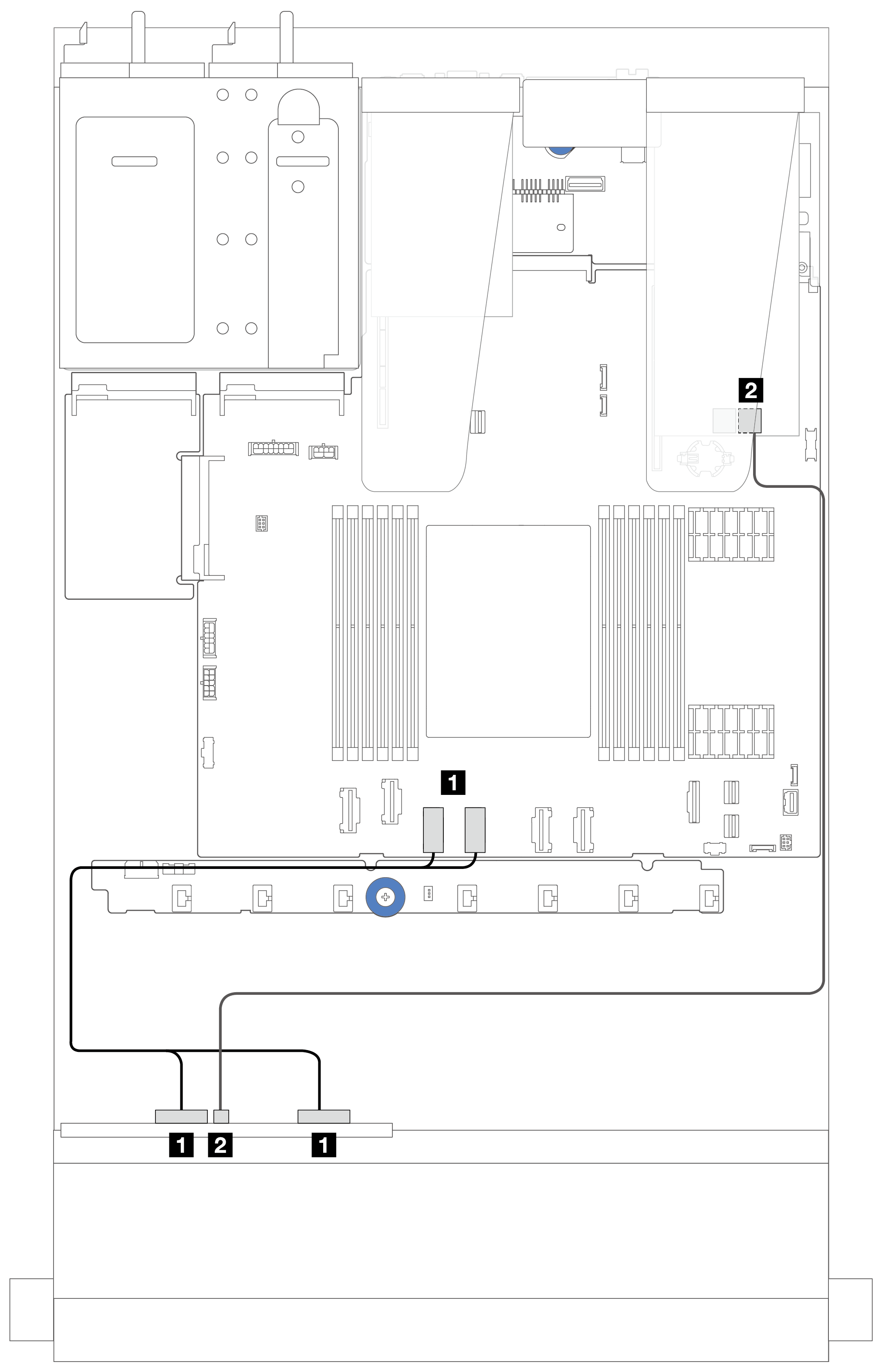
Note
Gen 3 and Gen 4 SFF RAID/HBA adapters are slightly different in their connectors, but the connection method is similar. The following illustration takes Gen 4 SFF RAID/HBA adapters as an example.
| From | To |
|---|---|
| 1 NVMe 2-3 and NVMe 0-1 on the front backplane | 1 PCIe connector 3 and 4 on the system board assembly |
| 2 SAS on the front backplane | 2 C0 on the SFF RAID/HBA adapter |
Give documentation feedback