Install the Lenovo Neptune Liquid to Air Module
Follow instructions in this section to install the Lenovo Neptune Liquid to Air Module (L2AM).
This task must be operated by trained technicians that are certified by Lenovo Service. Do not attempt to remove or install the part without proper training and qualification.
About this task

Read Installation Guidelines and Safety inspection checklist to ensure that you work safely.
| Torque screwdriver type list | Screw Type |
|---|---|
| Torx T20 screwdriver | Torx T20 screw |
Procedure
- If you have removed the radiator tray, install the radiator tray to the chassis.
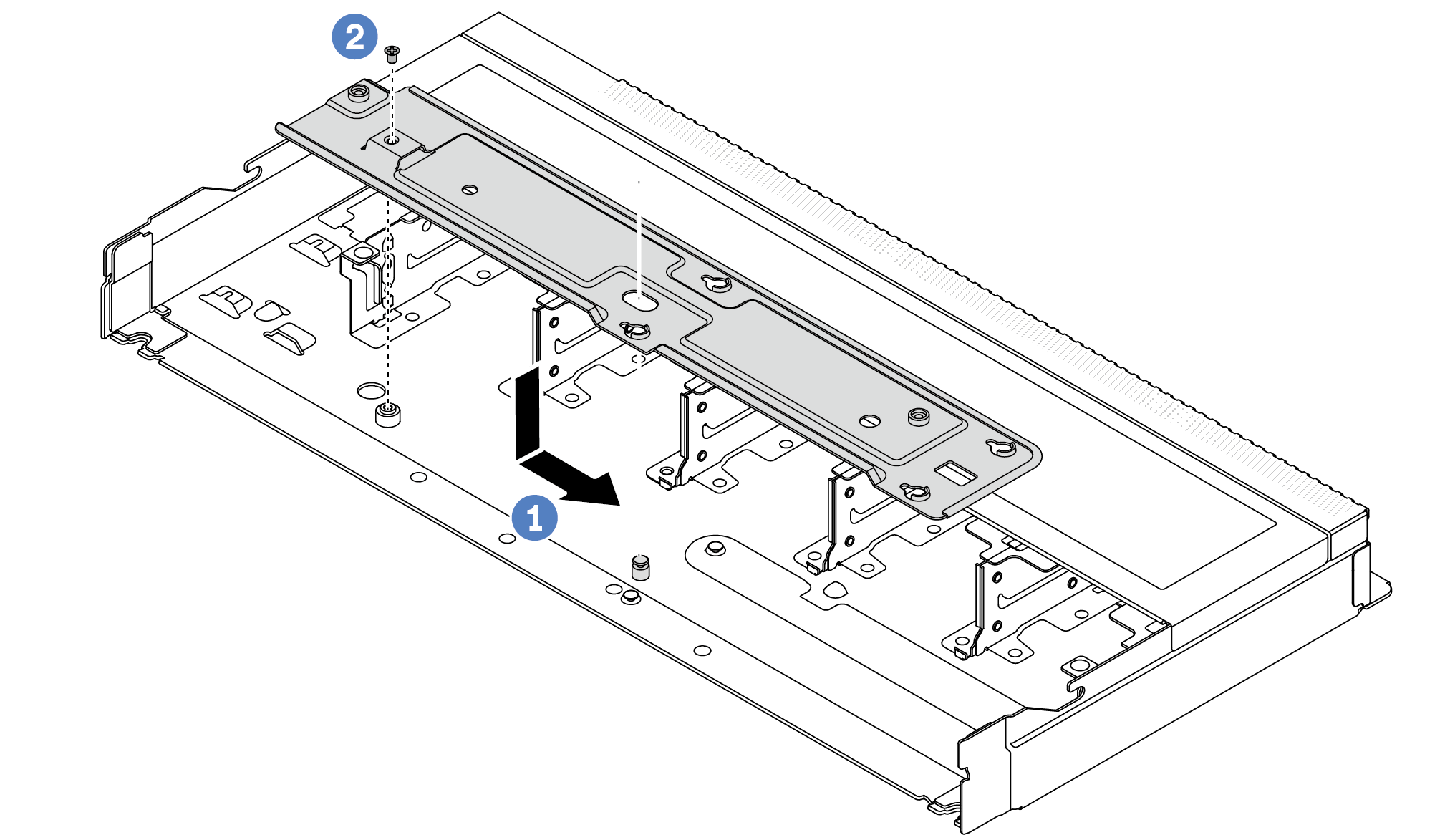
 Place the tray evenly into the chassis and then move it to the right so that the screw hole on the tray aligns with the hole on the chassis.
 Tighten the screw.
- Separate the L2AM module from the shipping tray.
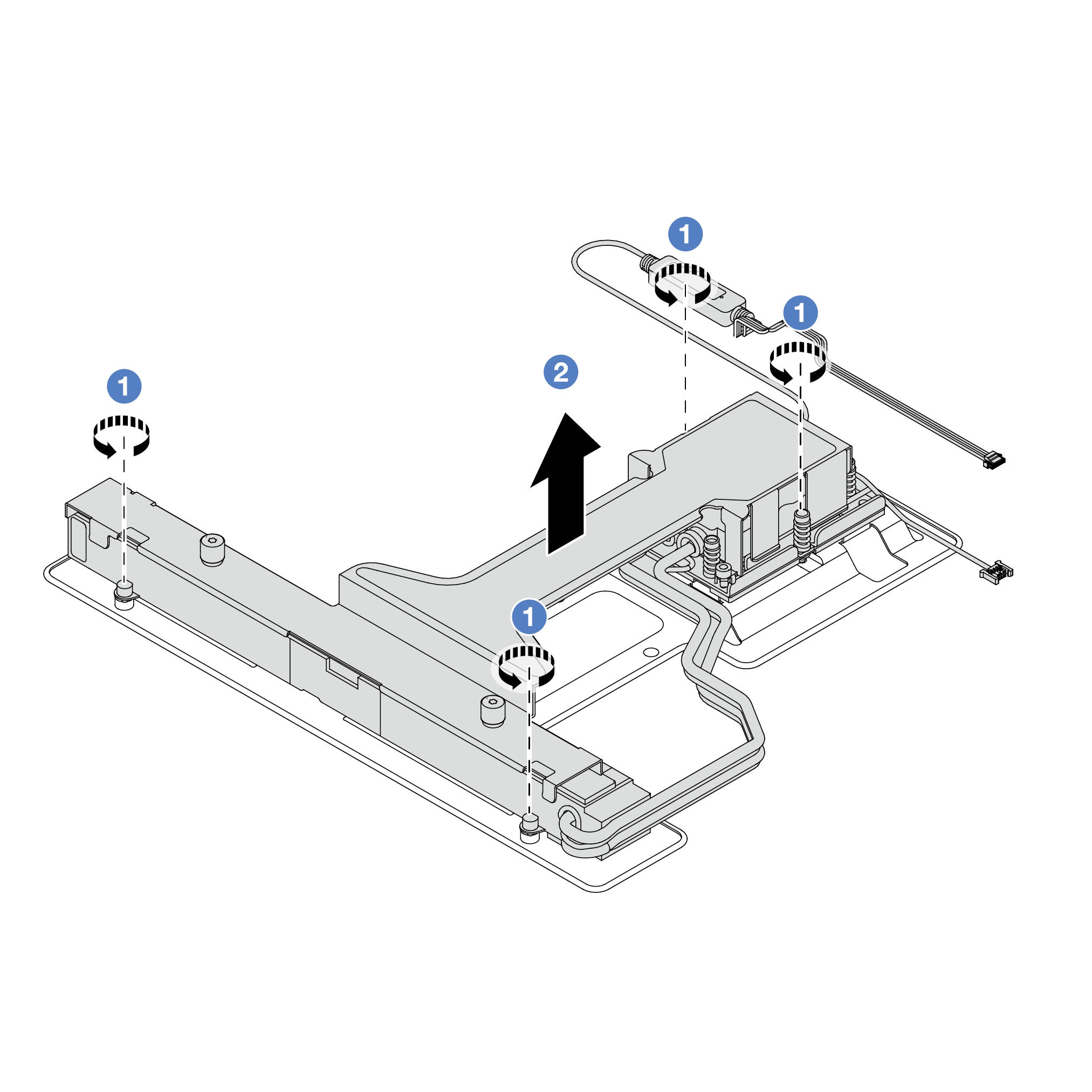
- Loosen the four screws on the L2AM shipping tray.
- Grasp the middle of the module handle (L2AM heat sink bracket) and one T20 screw fastening the radiator to lift the L2AM to separate the module from the shipping tray.
- Install the L2AM to the system board assembly.
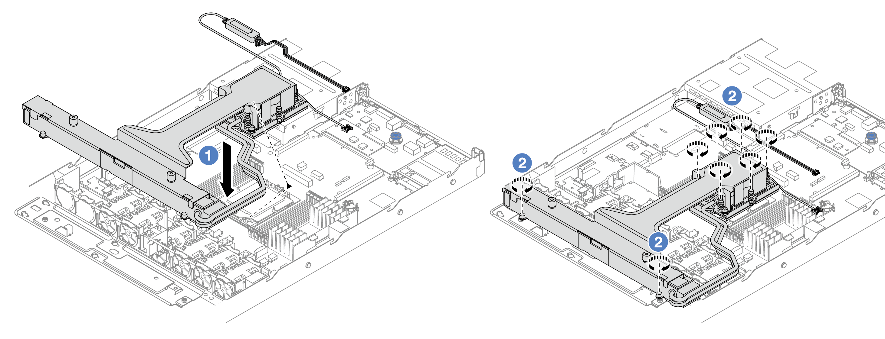
- Align the triangular mark on the cold plate assembly label with the triangular mark on the processor carrier and processor. Install the L2AM onto the processor-carrier. Press the carrier into place until the clips at all four corners engage.
- Fully tighten the eight Torx T20 nuts in the installation sequence shown on the cold plate assembly and the radiator. Tighten the screws and then, visually inspect to make sure that there is no gap between the screw shoulder beneath the cold plate assembly and the processor socket.
- Separate the module handle (L2AM heat sink bracket) from the module.
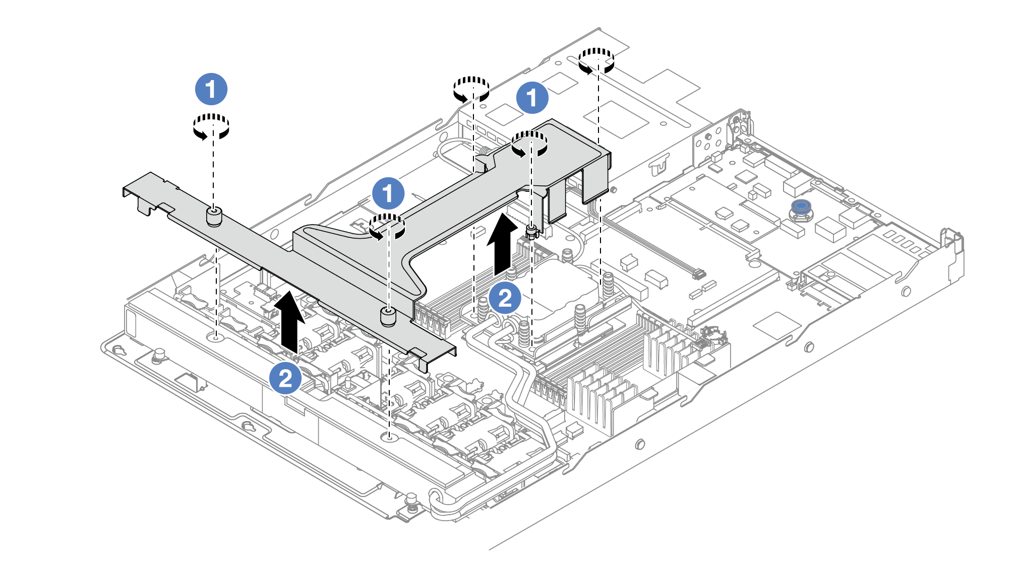
- Loosen the five screws on the module handle (L2AM heat sink bracket).
- Grasp the middle of the module handle (L2AM heat sink bracket) to separate it from the module.
- Install the leak detection module to the PSU air baffle.
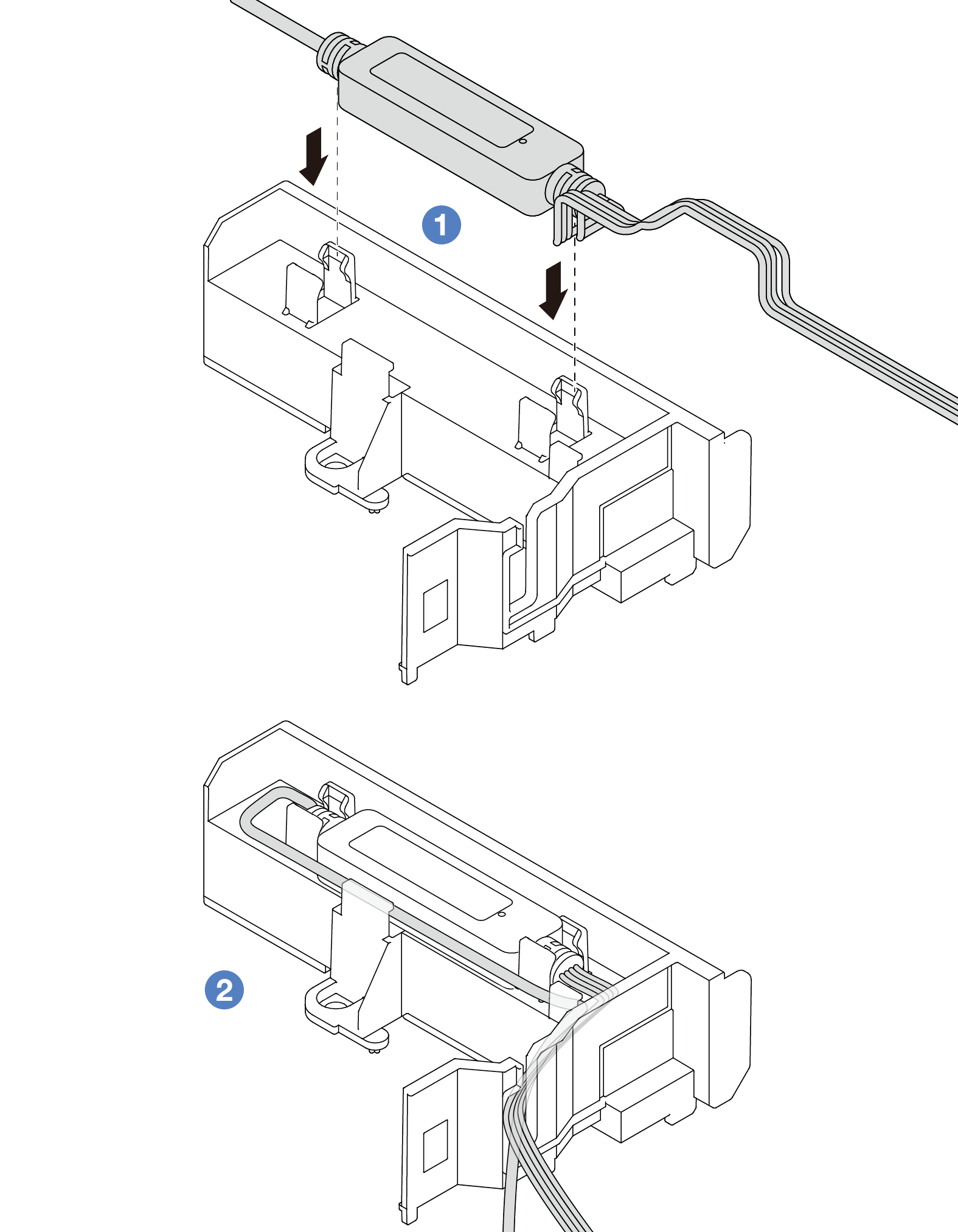
- Install the L2AM into the two clips on the PSU air baffle. Ensure that the module is secured in place.
- After the module is secured, route the cable through the cable clips to keep tidy for later cable routing arrangements.
NoteForliquid detection sensor module working status, see Liquid detection sensor LED.
After you finish
Install the backplane and the backplane cables if you removed them before. See Install the front 2.5-inch drive backplane and Power/Sideband cable routing.
Complete the parts replacement. See Complete the parts replacement.
Demo video